Hi Paulo,
Yes, no problem at all.
Cheers,
Panson
Great! 🙂 Thanks! 🙂
One other question: the big 0.22R 5W resistors, can they be 0.1R?
Thanks!🙂
Forget that.
LOL - I'm quoting mysefl!:😉
C1 values 390pF - Is 330pF OK?
Thanks! 🙂
According to my electronics book R2 and C1 make a low pass filter. The cut-off frequency will be 1/RC (rad/s). 2000x390x10^-12 = 7.8x10^-7 => w=1282051 rad/s = 204kHz ????? This must be wrong!!!
According to my electronics book R2 and C1 make a low pass filter. The cut-off frequency will be 1/RC (rad/s). 2000x390x10^-12 = 7.8x10^-7 => w=1282051 rad/s = 204kHz ????? This must be wrong!!!
Hi Paulo,
This is correct. If we set the cut-off freq at 20kHz, we will have to much phase shift at high frequencies. Setting it 10 times higher, we will have very little phase shift at 20kHz. You can use 330pF without problem.
Panson
One other question: the big 0.22R 5W resistors, can they be 0.1R?
Thanks!🙂
Sure, you can use 0.1R 5W.
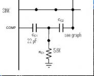
Two-pole compensation
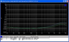
I implemented two-pole compensation to a LME49811 with ThermalTrak amp. The high-frequency distortion is reduced. Here is an example: 123W into 8 Ohm load. The result is very promising.
Cc1 = 22pF (single-pole cap)
Cc2 = 44 pF
Rc1 = 5.6 k
I implemented two-pole compensation to a LME49811 with ThermalTrak amp. The high-frequency distortion is reduced. Here is an example: 123W into 8 Ohm load. The result is very promising.
Cc1 = 22pF (single-pole cap)
Cc2 = 44 pF
Rc1 = 5.6 k
Attachments
Hi Paulo,
This is correct.
Today I feel less ignorant! 🙂
I tought my calculation was totaly wrong, due to my little knowledge of electronics!
Sure, you can use 0.1R 5W.
Are you sure? It's not going to blow up the mosfets?
Thank you Panson! 🙂
Are you sure? It's not going to blow up the mosfets?
Thank you Panson! 🙂
I presumed you are referring to BJT. I tested 0.1R with BJTs. You probably need at least 0.2R for MOSFET.
Last edited:
Is 0.22R the best value or should I use higher value than that?
Lower is better as long as the circuit is stable. I have used 0.22R with two pairs of IRFP240/9240 without any problem.
I implemented two-pole compensation to a LME49811 with ThermalTrak amp. The high-frequency distortion is reduced. Here is an example: 123W into 8 Ohm load. The result is very promising.
Yup, it is 🙂
I implemented two-pole compensation to a LME49811 with ThermalTrak amp. The high-frequency distortion is reduced. Here is an example: 123W into 8 Ohm load. The result is very promising.
Cc1 = 22pF (single-pole cap)
Cc2 = 44 pF
Rc1 = 5.6 k
Yea, that's good result.
Now, if you have time, please try Cc2 100pF, unsolder the Rc1 resistor and solder a 1k8 resistor between capacitors and the output with a wire, just like I have shown in my previous posts. The THD results should be similar but the impulse response should be the same as with the standard miller compensation. With two-pole compensation you have overshoot.
I implemented two-pole compensation to a LME49811 with ThermalTrak amp. The high-frequency distortion is reduced. Here is an example: 123W into 8 Ohm load. The result is very promising.
Cc1 = 22pF (single-pole cap)
Cc2 = 44 pF
Rc1 = 5.6 k
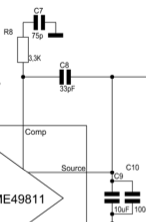
Dear Panson,
Such a distortion rise in the higher frequencies are sometimes suspective. Are you really sure that somewhere high in the MHz. range there isn't any oscillation?
I end up with this scheme, after advice from the National designer on this forum, and it killed the Mhz. range oscillation.
With kind regards,
Bas
Attachments
Dear Panson,
Such a distortion rise in the higher frequencies are sometimes suspective. Are you really sure that somewhere high in the MHz. range there isn't any oscillation?
[snip]
The THD diagram looks quite normal to me 😉
And that is not a two pole compensation.
Last edited:
The THD diagram looks quite normal to me 😉
And that is not a two pole compensation.
It isn't a two pole. I wanted to point this out, because I experienced myself oscillation's far away, which wasn't visible or noticeable on first sight. This compensation scheme solved it.
Btw. My example shows one error, the cap should be connected to the sink pin instead of the source 😉
With kind regards,
Bas
Dear Panson,
Such a distortion rise in the higher frequencies are sometimes suspective. Are you really sure that somewhere high in the MHz. range there isn't any oscillation?
I end up with this scheme, after advice from the National designer on this forum, and it killed the Mhz. range oscillation.
With kind regards,
Bas
I'm doing the exac same thing as Bas. It's from AudioMan54 (Mark) from the National Op Amp Inflation thread. I haven't had any problem with oscillation.
As I recall this compensation scheme was created to help the amp come out of clipping smoothly.
I have had issues with overshoot in the square wave with the zobel connected. Disconnected it goes away.
Ken
Dear,
Here square wave measurements. In this case the LME49810 with a pair of STD03's. Compensation only 10pF miller cap without the extra added filter. No sign of oscillation or overshoot, still it was oscillating at 10Mhz. With normal squarewave test or THD measurements I would't have seen it.
Resp: 1Khz. and 10Khz. Square wave.
With kind regards,
Bas
Attachments
Last edited:
Dear Panson,
Such a distortion rise in the higher frequencies are sometimes suspective. Are you really sure that somewhere high in the MHz. range there isn't any oscillation?
I end up with this scheme, after advice from the National designer on this forum, and it killed the Mhz. range oscillation.
With kind regards,
Bas
Hi Bas,
No sign of oscillation when tested with 8Ohm and 4Ohm resistive load. The output was monitored by a 500 MHz scope. I will make more test including square wave after Chinese New Year.
Panson
- Home
- Amplifiers
- Chip Amps
- Comparing LME49810, 49830 and 49811