panson_hk said:
Hi Shaun,
This is a three stages of emitter follower as the SPICE model below.
Are you going to use CFP or EF output configuration?
Panson,
the 15030 in the first position doesn't simulate so well. Leach uses a triple configuration and uses 2N3439 /2N5416 in the first position - I've also seen 2SD669/2SB649 in this location. Both perform much better in simulation in this location. Your thoughts?
Ken
klewis said:
Panson,
the 15030 in the first position doesn't simulate so well. Leach uses a triple configuration and uses 2N3439 /2N5416 in the first position - I've also seen 2SD669/2SB649 in this location. Both perform much better in simulation in this location. Your thoughts?
Ken
Ken,
Thank you for your input. I have not simulated other pairs for pre-driver. Do you refer to THD performance? What bias level did you use in your simulation module?
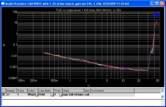
Here is some data from a warm-up test. The AP has been off for a while. I run THD vs output level for a 49811 multiple times. The test circuit Fig. 3 shown in 49811 data sheet was used with gain set resistors 51k and 1.65 k; and Cc = 22 pF.
Attachments
Great post and very informative.
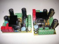
I too am designing power amps based on the LME49810. I have completed PCAs for the 810 chip, and just recently received my power output boards as well.
Attached is a pic of my driver board. It is 1/2 of one of ExpressPCB's MiniBoard service. So with one purchase, I ended up with 6 boards (6 audio channels).
My basic design is right off the data sheet with just a few changes. The output stage will be a triple-darlington emitter-follower design. Those boards are done too, and were basically free. Here's a link to my output boards and the free deal I used: http://www.diyaudio.com/forums/showthread.php?s=&threadid=145590
Thanks again for the great knowledge and technical dialog.
Regards,
Paul
Attachments
DCPreamp said:
I too am designing power amps based on the LME49810. I have completed PCAs for the 810 chip, and just recently received my power output boards as well.
Hi Paul,
Thank you! Please let us know your test results. Are you going to use 4 pairs output?
panson_hk said:
Hi Paul,
Thank you! Please let us know your test results. Are you going to use 4 pairs output?
I'm actually going to be using 8-pairs of TO-264 per channel. I'm planning on running the amp at +/- 90VDC and MAY try to run it full-tilt into 2 ohms. The transformers (1 per channel) are 1.4KVA, plus lots of outputs for lots of SOA should do the trick : )
foo said:Triple darlinton will be a good idea.
If they are not blown.
Why would they be blown? They'll be matched, well filtered, and properly cooled. Any advice you can recommend?
Thanks,
Paul
hi all
I have got a bunch of Sankens 2sc3264/2sc1295
a 1200va 2x 65v(unloaded) transformer, and some lme49811.
I am planning to built triple EF (Leach) output stage using:
- Five to six pairs of those Sankens as output devices
- 2sc5200/2sa1943 as drivers,
- 2sc5171 / 2sa1930 as pre drivers.
The drivers and pre-drivers will work in classA such as in the Leach output stage.
My question is: Are the driver's and pre- drivers choices correct?
Thanks for any advice.
the Leach driver stage is not ClassA.
Look at the currents in the drivers when alternate halves shut down. The driver current does not change. The other half is doing all the work.
Look at the currents in the drivers when alternate halves shut down. The driver current does not change. The other half is doing all the work.
Re: LME49830 on higher rails than output devices?
I've decoupled the LM4702 from the main supply rail with a small resistor -- but my amps generally use lateral MOSFETs which turn on at a low voltage to begin with (so the voltage is a few tenths LOWER).
I was thinking of exactly what was contained in your post -- and regulating the LM4702 a la Borbely's MOSFET designs. Just enough higher ...
RocketScientist said:There's some great info here on the LME498xx parts but I can't find anyone who's running the chip on slightly higher rails than the output devices to improve the overall efficiency when using MOSFETs.
As many here probably know, on the same rails, MOSFETs tend to have around 10% - 20% less output power than bipolars. So while having 2 sets of rails adds complexity, it also increases power output and/or allows the amp to run cooler.
I've decoupled the LM4702 from the main supply rail with a small resistor -- but my amps generally use lateral MOSFETs which turn on at a low voltage to begin with (so the voltage is a few tenths LOWER).
I was thinking of exactly what was contained in your post -- and regulating the LM4702 a la Borbely's MOSFET designs. Just enough higher ...
Hi Panson,
which load are you using for your THD-plot?
Would be interesting, as the numbers pretty strongly depend on it.
Have fun, Hannes
which load are you using for your THD-plot?
Would be interesting, as the numbers pretty strongly depend on it.
Have fun, Hannes
h_a said:Hi Panson,
which load are you using for your THD-plot?
Would be interesting, as the numbers pretty strongly depend on it.
Have fun, Hannes
No extra load except the System One 100 k input resistance.
Ouch 😉
Why not with a load? If you don't have a high power dummy, already the 1W figures would be interesting and are easy to do.
Have fun, Hannes
Why not with a load? If you don't have a high power dummy, already the 1W figures would be interesting and are easy to do.
Have fun, Hannes
panson_hk said:
Ken,
Thank you for your input. I have not simulated other pairs for pre-driver. Do you refer to THD performance? What bias level did you use in your simulation module?
Panson,
Yes, I am refering to THD. I set the bias at 2.8v. THD gets better if it's set higher - say 4.5v, but I don't know if the 49811 will got that high.
Ken
AndrewT said:the Leach driver stage is not ClassA.
Look at the currents in the drivers when alternate halves shut down. The driver current does not change. The other half is doing all the work.
Hi Andrew,
(refer to post 53 schematic)
I agree this does not look like class A.
Then, i can't understand what mr Leach means:
"The driver transistors are connected so that they all operate in the class-A mode."
line 18th into this page:
http://users.ece.gatech.edu/~mleach/lowtim/output.html
h_a said:Ouch 😉
Why not with a load? If you don't have a high power dummy, already the 1W figures would be interesting and are easy to do.
Have fun, Hannes
This is the driver chip only. For loaded data, please see previous posts of this thread.
bobodioulasso said:
Hi Andrew,
(refer to post 53 schematic)
I agree this does not look like class A.
Then, i can't understand what mr Leach means:
"The driver transistors are connected so that they all operate in the class-A mode."
line 18th into this page:
http://users.ece.gatech.edu/~mleach/lowtim/output.html
Hi,
look at it this way, driver transistors Q14,Q16 and Q15,Q17 have their emmiters tied by R36 for Q16/Q17 and the series connected R34/R35 on the emmiters of Q14/Q15....
now because of bias voltage from Vbe multiplier, quiscient curent flows accross these transistors at all times, they are never really cut-off by virtue of their connection, even if the output transistors themselves are cut-off...
do you follow me? it is in this context that they are classA...
Hi,
whether the transistor is forced to pass a non zero current or allowed to switch off, does not define or otherwise if it's operating in ClassA.
In single ended ClassA, the transistor must change current with the load current to remain in control of the output stage current.
In push pull ClassA both the upper half and the lower half must change currents with the load to remain in control of the output stage current.
Notice how closely the push pull mimics the action of the single ended.
If one or other of the push pull halves cuts off or goes into (near) constant current mode then it no longer operates in ClassA. It is now in ClassAB. At very low output currents it can be operating in ClassA, just like a ClassAB output stage has a small range of ClassA output current.
Leach is wrong in his assertion that ensuring non zero current in the non operating half is equivalent to ClassA operation. He's not alone this misunderstanding seems to be, somewhat surprisingly, common among designers
- Home
- Amplifiers
- Chip Amps
- Comparing LME49810, 49830 and 49811