The offset does not vary by pot setting; but I put 4.7microF caps at input and I read somewhere that in this way offset does not change.
But now is late in the night in Italy, I'll try to connect speakers tomorrow,
thank you Peter
Renato
But now is late in the night in Italy, I'll try to connect speakers tomorrow,
thank you Peter
Renato
Yes, that's correct, with caps the offset will stay at its highest level all the time.
I had 47Labs Gaincard, that also uses input coupling caps, and offset was approx 80mV, so yours is not that much off 😉
You may reduce input shunt resistor (R2) from 22k to 10k and that will lower the offset as well.
I had 47Labs Gaincard, that also uses input coupling caps, and offset was approx 80mV, so yours is not that much off 😉
You may reduce input shunt resistor (R2) from 22k to 10k and that will lower the offset as well.
You may try adding small cap as described here: http://www.diyaudio.com/forums/audi...-kit-building-instructions-3.html#post1516522
If that won't help, try adding Zobel (Rz 2.7R and Cz 0.1uF on amp board).
If noting helps, you may be forced to add some shielding to amp circuit.
I have some amp running without any enclosure and in my listening environment it's not a problem, but with other setups it may be different.
Panic over. Wooden box is fine. No need for adhesive aluminium shielding. No need for a metal case. No need for zobels. Damned cordless house phone was the culprit. Chucking out the "throbbing" EMI. I've read they're the absolute worst for radiation harmful to humans too (ie worse than mobile (cell) phones or Wi-fi). A metre further away resolved it completely.
Many thanks to Peter and all who helped.
Thanks for reporting Lucas, nice news...
Just for fun : I'm able to continue a call after I place the base of my DECT phone inside a stainless steel pressure cooker... and with the top cover in place !!!
Seems now "Low Radiation cordless DECT phones" exist, they don't have to permanently communicate with their base...
Welcome to the Frontpage
Not so easy to buy however... 🙁
Steele Hammond Chassis with Walnut side Panels -> 7" x 5" x 2"
Hammond Mfg. - Steel Chassis & Bottom Plates with Walnut Side Panels (1441 CWW & 1431 Series)
This looks like a pretty good option for the shigaclone. I'm sure you can fit the assembly into it, and finish the top off with a sheet of frosted plexiglass.
Hammond Mfg. - Steel Chassis & Bottom Plates with Walnut Side Panels (1441 CWW & 1431 Series)
This looks like a pretty good option for the shigaclone. I'm sure you can fit the assembly into it, and finish the top off with a sheet of frosted plexiglass.
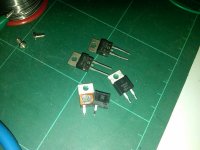
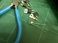
I have accidentally burned two mur860 in one channel. Can these to replace with MUR890? I am building Peter's LM gainclones (monoblock). Also, the LED light in the other monoblock seems to be turning off very slowly. It took a minute for it to turn off. The rail is at 27v. transformer is 2 x 25vdc. DC offset is at 80mv. what is wrong?
In picture 011.jpg, the bottom two mur860 are the ones which burned and the ones above are the mur890. The LED is shown in 013.jpg. I used a 62k resistor at R3.
In picture 011.jpg, the bottom two mur860 are the ones which burned and the ones above are the mur890. The LED is shown in 013.jpg. I used a 62k resistor at R3.
Attachments
Last edited:
LED turns off slow because you have capacitance that keeps it glowing until the capacitor is completely discharged. If you are using a regular LM3886 or LM3875 you do not need better than MUR860. How in the heck did you destroy one of those diodes?!
IF you have MUR890 laying around it will do the same job as the MUR860
IF you have MUR890 laying around it will do the same job as the MUR860
Last edited:
Yes...but lights goes off in 1 minute???
Sigh..it was a stupid mistake...the v+ and the pg+ from the psu was suppose to connect to the v+ and pg+ of the main board....and i connect the pg+ of the psu to the 'chg' of the main board...and the v+ of the psu to the pg+ of the main board. Heard the transformer buzzz but I thought it was humm and then 'pop'..spark flew and i have two destroyed diode. i am using the LM3875. Can I sub the two mur860 with the mur890? I have the 890 but not the 860.
Sigh..it was a stupid mistake...the v+ and the pg+ from the psu was suppose to connect to the v+ and pg+ of the main board....and i connect the pg+ of the psu to the 'chg' of the main board...and the v+ of the psu to the pg+ of the main board. Heard the transformer buzzz but I thought it was humm and then 'pop'..spark flew and i have two destroyed diode. i am using the LM3875. Can I sub the two mur860 with the mur890? I have the 890 but not the 860.
Last edited:
Yes, the huge capacitance can run a little LED for a very long time. Yes the 890 is fine. Lets hope the chip is okay.
Uriah
Uriah
Thanks for confirmation. The chip is fine...tested it with the other psu board and the dc offset is at 79mv. and the other around 80mv
buzzz
when i connect my amp to the speaker, the speaker emits a buzzing sound. And when i connect the rca, the buzz became louder. why?? Is the chip too close to the power?
when i connect my amp to the speaker, the speaker emits a buzzing sound. And when i connect the rca, the buzz became louder. why?? Is the chip too close to the power?
I've just finished building the chassis for my gainclone. While putting in connectors I realized that the RCA connectors I've bought have the outer sleeve connected to the chassis. Is this bad? It seems like Peters connectors are isolated from the chassis.
In short: Yes, it IS bad. You have to buy RCA's which are fully isolated to avoid grounding problems. You will most certainly get a humming noise with the signal ground connected to the chassis via the RCA plugs.
Martin
Martin
dc after the diodes are 37.8v.
rail at 28.35v.
why is there a buzzing sound?
is the chip dead?
do i need to ground the pcb?
rail at 28.35v.
why is there a buzzing sound?
is the chip dead?
do i need to ground the pcb?
Last edited:
pcb grounded but buzzing still exist. i think it is the rca. when connect to cable, the buzz becomes very loud
In short: Yes, it IS bad. You have to buy RCA's which are fully isolated to avoid grounding problems. You will most certainly get a humming noise with the signal ground connected to the chassis via the RCA plugs.
Martin
Thanks Martin. I'll see if I can get some isolated RCA's.
pmchoong, please make sure of these things:
1: As with the other gentleman your rcas should be insulated from the chassis. (its okay that they touch but it can cause ground loops which will buzz)
2: Do you have signal going to signal or do you have signal and ground switched around on your RCA plugs?
3: this buzzing can be caused by bad solder joints and if you made your own RCA cable there could be bad joints there or you could have bad joints in your input RCA jacks on your chassis.
4: solder joints could be bad at signal input to amp boards.
That covers bad solder joints I guess. Another thing to try is this:
With ground loop problems sometimes just touching signal wires, heatsinks, volume pots with our fingers can cause the hum to increase and then we know we have a grounding problem. With the amp on try this out. Wiggle the wires, touch the volume pot, touch the heatsink. Does the hum/buzz change when you do this?
Take some pictures. Lets see whats going on here.
The fact that it gets louder when you connect the RCAs makes me think that there is a bad solder joint that goes to ground. Check extra carefully for that and if you DIYed your own preamp check that on another piece of equipment to make sure its not part of the problem.
Uriah
Nis,
This might or might not be a problem. If you want to know before you spend the money then simply remove them from the chassis and plug them back together and see if you get the same problem.
Uriah
This might or might not be a problem. If you want to know before you spend the money then simply remove them from the chassis and plug them back together and see if you get the same problem.
Uriah
Nis,
This might or might not be a problem. If you want to know before you spend the money then simply remove them from the chassis and plug them back together and see if you get the same problem.
Uriah
The only problem, yet, is that I need to drill some bigger holes in the chassis. I haven't actually done any soldering apart from putting the components on the board. I was just asking because Peter's connectors seems to be grounded and all connectors I could find around where I live were not isolated from the chassis.
I have ordered a pair of these: Pair Gold Plated RCA Phono Chassis / Panel Sockets on eBay (end time 25-Aug-10 19:41:50 BST)
- Home
- More Vendors...
- Audio Sector
- Commercial Gainclone kit- building instructions