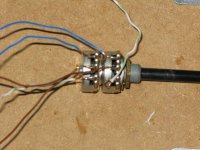
westers - you seem to have both channels connected to one pot - each channel should be using a set of three connections. There seem to be wires from the front pot to the rear pot. Please look at the early posts in this thread for how they need to be connected.
Also what is that white cable disappearing under the board?
Also what is that white cable disappearing under the board?
Alan
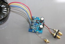
Ignore the last photo as it's a bit misleading on the amp/pot side of things - that was just to show the rectifier connections to the amp PCB's.
Here's a blurry view of the pot - dual gang - the white wire is the input from each RCA, the blue wires are the earth connections, and the brown wires are the outputs from the pot to the amp board.
Each of those wires connects as per my description in post #435 above.
Attachments
Also I only have one PG+ and PG- connected from the rectifier board to the star ground as per Peter's description.
The star ground is attached to the OG connection on each Amp pcb.
The star ground is attached to the OG connection on each Amp pcb.
Transformer was connected as per your instructions - one rectifier board with two bridges, one secondary going to one pair of AC connectors, the other secondary going to the second pair of AC connectors.
When I measured the voltage it was 24V for each bridge output, but that was 10V down on what each secondary was rated at (35V). However there was no load whatsoever.
I now think I've broken something - I tried connecting just one channel, but when I switched on (with the lightbulb tester) there was a loud bang. I swicthed off and nothing looked burnt out, so I connected both channels back together as per the instructions in this thread.
However I'm now getting DC offset readings that go off the voltmeter scale - way over 100mv offset.
Just taken the circuit apart and measured the voltages out of the bridge. I'm getting -23.6V and +23.6V.
Secondaries are 25V
Secondaries are 25V
Hi, try connecting 1 board with non of the in and out wires connected. That is just V+, V- and ground connected and see if you can take any readings (across V+ to V-) and if OK take the reading between OUT and Gnd (star) ..
With dual secondaries connected to the single rectifier, how do I make sure only one secondary is actually powering the single board?
Also, can you explain exactly how to ground the single board. The reason I ask is because I tried doing this earlier on and that's when I got a big bang from the circuit and then all hell broke lose with my DC offset 🙁
Thanks
Also, can you explain exactly how to ground the single board. The reason I ask is because I tried doing this earlier on and that's when I got a big bang from the circuit and then all hell broke lose with my DC offset 🙁
Thanks
Both secondaries power a single board as single board requires symmetrical supply (+/-V)
You ground it the same way as with 2 boards you had previously: connect both PG+ and PG- to OG, or to corresponding pads on amp board (PG+, PG-)
You ground it the same way as with 2 boards you had previously: connect both PG+ and PG- to OG, or to corresponding pads on amp board (PG+, PG-)
Thanks guys.
Apologies for the heavy support needed to get this going, but much appreciated for the help and patience shown.
Apologies for the heavy support needed to get this going, but much appreciated for the help and patience shown.
Ok, here are the readings.
With two 25V secondaries connected and going to one amp board I get 72V between V+ and V- on the amp pcb, and 49V between OUT and SG on the amp board.
With two 25V secondaries connected and going to one amp board I get 72V between V+ and V- on the amp pcb, and 49V between OUT and SG on the amp board.
Well it looks as if that Amp is damaged, Peter may have more idea.
Try the other Amp and see if the DC offset is nothing like as bad as the 49V of the first Amp..
Try the other Amp and see if the DC offset is nothing like as bad as the 49V of the first Amp..
Ok, have done that and it looks like the amp that was connected when I previously tried to connect it as a mono is broken.
The second amp measures 72V across V+ and V-, but only -1.1mv between OUT and SG.
Compare that to the 47V for the other amp and I've now answered the question why my DC offset has gone AWOL.
I'll order another chip from Farnell and replace the damaged one.
Now, it still doesn't explain why I got no output before I blew up one of the amp chips. 🙁
Connect the good amp as in Peter's picture that I posted without the volume control. You can use the volume control on your source item.
It works😀 😀 😀 😀 😀 😀
But the really, really sad thing is that I've been chasing my tail trying to get it to work, blown up one chip amplifier, and have finally discovered that I'd made a really simple and very, very stupid error. It's so embarrasing that I'm not going to say what it was, suffice to say that it wasn't anything to do with the circuit board or volume connections.
Sounds good on one speaker, maybe a touch bright for my liking, but I'll have to reserve judgment until I get the other channel working and the components have broken in.
If it's still a bit treble heavy for my taste what "tuning" can I do mellow the sound a little?
Quick update - WOW!!
I now realise that my original impression of it being a bit bright was due to poor original recording and a lifetime of listening to equipment that hid this from my ears.
Get a well recorded piece of music playing and it's amzing, but I now have to recalibrate my brain a touch.
And this is just one channel through one speaker!!!!
Can't wait to get the other channel working.
My transformer is 140VA, 24V secondaries, am I just going to have low power or will I damage the chips in some way?
That transformer should not create any problems, it's just might not be able to provide enough current at power peaks, but then again, you may never need it.
- Home
- More Vendors...
- Audio Sector
- Commercial Gainclone kit- building instructions