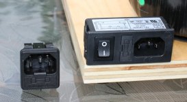
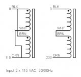
I will start with connecting transformer primaries. In case of dual primaries, you can connect them either in parallel (to match 115V mains) or in series, to match 230V mains as per attached diagram (courtesy of Plitron).
The neutral wire from the mains connects to the transformer wire marked with dot, which is the start of the winding.
The wires are color coded, and may differ for other manufacturers.
The neutral wire from the mains connects to the transformer wire marked with dot, which is the start of the winding.
The wires are color coded, and may differ for other manufacturers.
Attachments
Of course, don't forget about the fuse and use slow blow version. With 300VA transformer and no soft start, at least 4A rating is required (with 115V mains). In some instances even that blew occasionally so I normally use 5A SB fuses.
For 230V regions that would be half the fuse value.
For 230V regions that would be half the fuse value.
Attachments

Torroidal transformer are not available in my country, have search but come to no avail.
A standard transformer with center-tap would be the next choice of mine, how much amp does it need to supply just a mono amp? i wanted to build for my guitar amp. would a 5A with 22v-0v-22v transformer adequate?
A standard transformer with center-tap would be the next choice of mine, how much amp does it need to supply just a mono amp? i wanted to build for my guitar amp. would a 5A with 22v-0v-22v transformer adequate?
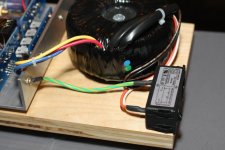
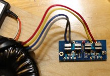
There is a spot for a LED on rectifier board and I like the small Panasonic LEDs available from DigiKey (part# P612). With those LEDs, 62K series resistor is required (R3 on rectifiers board, the long pin from the LED connect to square pad).
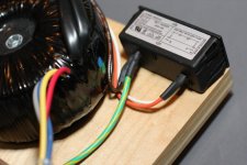
So the transformer is connected; before connecting rectifier board to the amp board we need to test voltages first.
If you didn't make any mistake, the simple test would be observing if LED lights up properly, but I will describe more appropriate method tomorrow 😉
So the transformer is connected; before connecting rectifier board to the amp board we need to test voltages first.
If you didn't make any mistake, the simple test would be observing if LED lights up properly, but I will describe more appropriate method tomorrow 😉
Attachments

casiomax said:Torroidal transformer are not available in my country, have search but come to no avail.
A standard transformer with center-tap would be the next choice of mine, how much amp does it need to supply just a mono amp? i wanted to build for my guitar amp. would a 5A with 22v-0v-22v transformer adequate?
Sure, it will do. The info how to connect centertapped transformer to rectifier board was posted here: http://www.diyaudio.com/forums/showthread.php?postid=1196283#post1196283
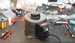
It's time to power up the circuit and test voltages.
With a new circuit, it's a good idea to increase mains voltage slowly, starting from 0V all way up to 120V and monitor current draw, voltages and components temperature. For that purpose I use Variac (Variable Auto Transformer).
Alternatively you may consider "common 100 watt lightbulb wired in series with the mains supply" as described on Nuuk's site: http://myweb.tiscali.co.uk/nuukspot/decdun/gaincloneFAQ.html#gcfaq1
It's also a good idea to use safety glasses 😎
With a new circuit, it's a good idea to increase mains voltage slowly, starting from 0V all way up to 120V and monitor current draw, voltages and components temperature. For that purpose I use Variac (Variable Auto Transformer).
Alternatively you may consider "common 100 watt lightbulb wired in series with the mains supply" as described on Nuuk's site: http://myweb.tiscali.co.uk/nuukspot/decdun/gaincloneFAQ.html#gcfaq1
An externally hosted image should be here but it was not working when we last tested it.
It's also a good idea to use safety glasses 😎
Attachments
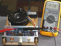
And between V- and PG- (black probe on PG)
If we measure approx. +/- 20V (positive will be lower because of LED) we are ready to connect amp boards.
Please note that voltages are much lower than expected beacuse of lack of smoothing caps.
If you have 10uF caps installed on rectifiers board both voltages would exceed 30V DC
If we measure approx. +/- 20V (positive will be lower because of LED) we are ready to connect amp boards.
Please note that voltages are much lower than expected beacuse of lack of smoothing caps.
If you have 10uF caps installed on rectifiers board both voltages would exceed 30V DC
Attachments
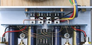
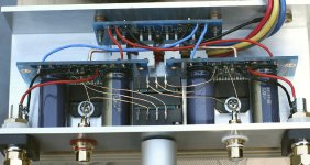
The important aspect about sharing a single transformer and common rectifiers per two amp channels is power star ground.
While you could simply run PG+ and PG- (ground) wires from rectifier board to each amp board, in some setups hum problems were reported and presently I always use star (power) ground in all my amps.
I simply achieve it by connecting output grounds (OG, on the opposite side of speaker wire connection) with a 14ga solid core copper wire.
The center of that wire is my power star ground and both PG+ and PG- grounds from rectifier board connect here. In the picture below the connections are so short that I used single runs of wire, normally I use two wires for both PG+ and PG-.
Please note that power ground is also directly connected to the chassis.
I specifically refer to it as power star ground, as signal wires from RCAs are not connect directly here. They connect through separate traces on PCB to OG (output ground) pads.
Attachments
More info on star and safety grounding was posted here: http://www.diyaudio.com/forums/showthread.php?postid=1509392#post1509392
If you need to implement ground break circuit between amp's power ground and chassis, you may consider the use of thermisor (CL60) as per F series of amps from Pass Labs.
I get my high gauge copper wires from electrical cables available at Home Depot.
If you need to implement ground break circuit between amp's power ground and chassis, you may consider the use of thermisor (CL60) as per F series of amps from Pass Labs.
I get my high gauge copper wires from electrical cables available at Home Depot.
Attachments

I specifically refer to it as power star ground, as signal wires from RCAs are not connect directly here. They connect through separate traces on PCB to OG (output ground) pads.
Should that read SG (signal ground) pads, Peter?
You are correct, wires from RCAs connect to SG (signal ground) pads. Signal star ground (on the board) connects with separate traces to OG pads, which are directly connected to the ground plane: http://www.audiosector.com/images/lm3875_se_pcb.gif
The first thing we do before connecting any speakers to the amp is measuring the DC offset. This can be done directly at the binding posts with no load connected. If the potentiometer is installed, the offset will vary depending on volume setting. This particular amp (right channel) measures 32mV offset when volume is completely down (input shunted to ground).
Attachments
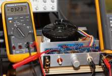
and 70mV when volume is at the maximum (15K combined input impedance of 50k pot and 22k input shunt resistor)
This is rather average chip when comes to offset, and for selected ones the offset is usually at 50mV or less at max setting.
The offset will be also lower when low impedance output preamp is connected.
When we switch the amp off and no speakers are connected, we can observe that for a moment or two the offset jumps pretty high to 4V or so. This is normal behaviour, and when load is connected (you may try it with 10R resistor across binding posts) the offset will stay low when turning the amp off.
Attachments
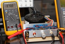
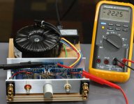
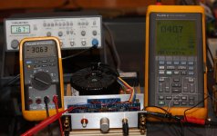
We'll also measure the power into 8ohm using dummy load connected to the amp's output (4 x 30R, 50w resistors) and feeding the amp with 100Hz sine wave. The measurement is taken before amp starts clipping.
At +/- 30.6V rails, the output voltage is approx 18V RMS with the input signal of 550mV. This translates into 40W output.
During such test, the heatsinks are way too small and the temperature rises substantially. At normal listening material and average levels though, the heatsinks are still fine.
At +/- 30.6V rails, the output voltage is approx 18V RMS with the input signal of 550mV. This translates into 40W output.
During such test, the heatsinks are way too small and the temperature rises substantially. At normal listening material and average levels though, the heatsinks are still fine.
Attachments
- Home
- More Vendors...
- Audio Sector
- Commercial Gainclone kit- building instructions