<< Vcc+ and Vee- are not a feed-and-return pair >>
Sure they are. You can do the math if you like, or you can just look.
R is the load, which is the op amps. Whether output (volume) is zero or non-zero, each op amp consumes perhaps 10ma--something--to operate. Circuit complete.
.
Most power amplifiers and op amps are class B for most of the waveform, so the supply current drawn by the output signal
largely goes to the load, and then to ground, not to the other power supply. Only the output stage bias current flows in the path shown.
Don't be silly. I deal with both positive current and negative currents for a living.There's no such thing as "positive current." Where this fairy tale come from, or why anybody perpetuates it, is one of the mysteries of our time.
.
Engineers are taught that current flows from positive to negative. This is of course, opposite of the direction of flow for the electrons. This causes no end of difficulty with physicists who work with electron beam synchrotrons, as they always work with the left hand rule, whereas we engineers were taught the right hand rule.
Blame Benjamin Franklin for the error; he had a 50% chance of getting the charge carriers correct, he chose wrong.
So when an engineer says positive current, one means current from the positive rail towards the load and negative rail. When a physicist speaks of positive current, they may be speaking of electrons, or positive charges. I could have easily said negative current from the - rail, as the argument is the same. But you felt the need to attempt some silly garbage instead of understanding the discussion.. Again, I find that tactic consistent with a high schooler learning google (not well, I might add).
No such thing as positive current? Try to convince a high energy particle physicist who operates a heavy ion particle accelerator or collider. They accelerate ions of silicon, gold, lead, and even uranium with all electrons stripped from the atoms, leaving a positively charged beam of particles travelling close to the speed of light, with an attribute the physicists call "beam current", as they define current as the transport of charged particles.
Heck, even the polarized proton physicists call the level of protons in the beam "current".
Anything original to say, or are you going to keep spouting silly, idiotic things in lieu of discussion?
jn
Last edited:
Blame Benjamin Franklin for the error; he had a 50% chance of getting the charge carriers correct, he chose wrong.
Yeah, what a moron. 😛 JK. I don't get why when physicists/engineers realized that the opposite was true for the flow of electrons, they just didn't do away with the incorrect way of thinking completely. Isn't that kind of like still passing around as common knowledge that the Earth is the center of the universe? I thought science wasn't supposed to be sentimental.
Yeah, what a moron. 😛 JK. I don't get why when physicists/engineers realized that the opposite was true for the flow of electrons, they just didn't do away with the incorrect way of thinking completely. Isn't that kind of like still passing around as common knowledge that the Earth is the center of the universe? I thought science wasn't supposed to be sentimental.
It does give no end of problems. I had to polarity check about a thousand magnets for an electron synchrotron, and the arguments with the beam physicists was never ending. They finally quieted down when the machine worked perfectly the first shot.
jn
.
So it's decided that Vee and Vcc are, in fact, a feed-and-return pair, on this there's agreement. As long as you're not too picky about what you call agreement.
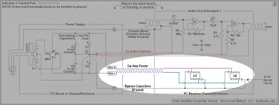
Re-posting the two circuits from post #337, the third circuit here is a further simplification. We find that:
In effect the op amp is a variable voltage divider--a high speed potentiometer.
Line Vcc: current can be anything, voltage cannot change.
Line Vee: current can be anything, voltage cannot change.
"Output Circuit" can be any current at any voltage.
Line "Circuit Ground = Zero Volts" is, by definition, zero volts.
These being the conditions, are Vee and Vcc still a feed-and-return pair?
A nod of respect to rayma, and to jneutron, both of whom did give a passing thought to addressing the question.
.
So it's decided that Vee and Vcc are, in fact, a feed-and-return pair, on this there's agreement. As long as you're not too picky about what you call agreement.
Re-posting the two circuits from post #337, the third circuit here is a further simplification. We find that:
In effect the op amp is a variable voltage divider--a high speed potentiometer.
Line Vcc: current can be anything, voltage cannot change.
Line Vee: current can be anything, voltage cannot change.
"Output Circuit" can be any current at any voltage.
Line "Circuit Ground = Zero Volts" is, by definition, zero volts.
These being the conditions, are Vee and Vcc still a feed-and-return pair?
A nod of respect to rayma, and to jneutron, both of whom did give a passing thought to addressing the question.
.
Attachments

Last edited:
.
So it's decided that Vee and Vcc are, in fact, a feed-and-return pair, on this there's agreement. As long as you're not too picky about what you call agreement.
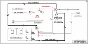
Not correct. The line you are showing passes only quiescent current, which is dc. No inductance at dc, there is no magnetic field (only with varying current), hence no need to twist these two (due to Iq).
for output current:
when the input signal is +ve, the output current to the load will be supplied by the +ve rail and it will return to ground (not to the -ve rail).
So you need to twist the Vcc with ground.
when the input signal is -ve, the output current to the load will be supplied by the -ve rail and it will return to ground (not to the +ve rail).
So you need to twist the Vee with ground.
End result : you twist the vcc, vee and ground together. Hope this makes it clear.
For completion sake, i should add that this is for non inverting. For inverting, you can reverse the polarities mentioned.when the input signal is +ve, the output current to the load will be supplied by the +ve rail and it will return to ground (not to the -ve rail).
So you need to twist the Vcc with ground.
when the input signal is -ve, the output current to the load will be supplied by the -ve rail and it will return to ground (not to the +ve rail).
So you need to twist the Vee with ground.
Not correct. The line you are showing passes only quiescent current, which is dc. No inductance at dc, there is no magnetic field (only with varying current), hence no need to twist these two (due to Iq).
for output current:
when the input signal is +ve, the output current to the load will be supplied by the +ve rail and it will return to ground (not to the -ve rail).
So you need to twist the Vcc with ground.
when the input signal is -ve, the output current to the load will be supplied by the -ve rail and it will return to ground (not to the +ve rail).
So you need to twist the Vee with ground.
End result : you twist the vcc, vee and ground together. Hope this makes it clear.
I went to a lot of trouble, earlier in this thread, to try to point out that this view is fundamentally flawed.
The return current from the load flows, in most systems for several feet, in a wire stretching from the speaker to the amplifier. This wire commonly has no rail conductor near it for the majority of its length and in the very large majority of systems is returned to a spur at the midpoint of the PSU caps. This is to prevent these large currents polluting more sensitive parts of the amplifier.
The positive and negative rails are both at AC ground, and neither carries only DC.
The currents that are of real concern are the half wave pulses drawn from the rails (in a class B or AB amplifier) as the signal moves alternately positive and negative. It is these currents which eventually find their expression in the amplifier output as distortion and it's the propagation of these signals which twisting of the rails is intended to prevent. Most of it couples from one rail into the other, and the inclusion of a ground wire is not critical, because the rails are at AC ground. Most power rails are tied to ground at numerous points by caps, to say nothing of those which are supplied by batteries.
Are we not supposed to minimize the loop area? If I twist the +ve and -ve rail together, but not the ground, When the load current is flowing in +ve rail and the ground, +ve rail and ground are far away and not twisted, wont that cause a much larger loop area.
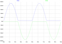
Same for class AB power amp. The rails are half wave pulses at the OP fundamental with lots of harmonics.
The idealized current flow path is from the conducting rail, out to the load, back to the source and from there back to the main star ground along with the power supply rails.
So, twisting the power ground, load return ground and both supply rails will minimize the radiating area.
The idealized current flow path is from the conducting rail, out to the load, back to the source and from there back to the main star ground along with the power supply rails.
So, twisting the power ground, load return ground and both supply rails will minimize the radiating area.
Originally Posted by Mark Whitney View Post
Bentsnake,............... For one, Vcc+ and Vee- are not a feed-and-return pair. Is it so difficult to do a current analysis?
Admirable intensity. But let's look at the facts.
<< Vcc+ and Vee- are not a feed-and-return pair >>
Sure they are. You can do the math if you like, or you can just look.............
.
You need to learn the difference between quiescent current in the opamps, and load current.
Positive current into the load comes from the + rail, to the load, then to the supply via the return conductor, NOT the - rail.
You are correct, teams of engineers have indeed done the heavy lifting. You need to understand what they actually did.
This is actually very easy engineering, I am quite surprised that you still haven't learned it.
jn
.
So it's decided that Vee and Vcc are, in fact, a feed-and-return pair, on this there's agreement. As long as you're not too picky about what you call agreement.
......................
Bents,Not correct. The line you are showing passes only quiescent current, which is dc. No inductance at dc, there is no magnetic field (only with varying current), hence no need to twist these two (due to Iq).
for output current:
when the input signal is +ve, the output current to the load will be supplied by the +ve rail and it will return to ground (not to the -ve rail).
So you need to twist the Vcc with ground.
when the input signal is -ve, the output current to the load will be supplied by the -ve rail and it will return to ground (not to the +ve rail).
So you need to twist the Vee with ground.
End result : you twist the vcc, vee and ground together. Hope this makes it clear.
how many times do you need to be told?
+ve rail and -ve rail of a dual polarity supply are NOT a Flow and Return Pair.
The Flow and Return PAIRS are
+ve rail and it's Return to PSU
-ve rail and it's Return to PSU.
Because the Return to PSU is the same wire/trace/bus/cable for both the +ve current return and for the -ve current return, you have to take the two sets of Flow and Return pairs as a 3wire triplet consisting of +ve rail, -ve rail and Return to PSU.
The +ve currents to the load FLOW at a DIFFERENT TIME from the -ve currents to (or from) the load.
You can't use D.Self as an example that breaks this pairing. He has not got it yet, not even in 6th edition.
Last edited:
Your question is correct.Are we not supposed to minimize the loop area? If I twist the +ve and -ve rail together, but not the ground, When the load current is flowing in +ve rail and the ground, +ve rail and ground are far away and not twisted, wont that cause a much larger loop area.
The loop area must include both the Flow and Return wires for the current flowing at that instant.
In a later or earlier instant it could be a different pair.
The Flow and Return PAIRS are
+ve rail and it's Return to PSU
-ve rail and it's Return to PSU.
Because the Return to PSU is the same wire/trace/bus/cable for both the +ve current return and for the -ve current return, you have to take the two sets of Flow and Return pairs as a 3wire triplet consisting of +ve rail, -ve rail and Return to PSU.
The +ve currents to the load FLOW at a DIFFERENT TIME from the -ve currents to (or from) the load.
Would it not make more sense to run two twisted pairs, vcc+ground and vee+ground. lower impedance of the twisted pair would ensure that the return current is flowing in the correct ground wire. This probably could work better at keeping these half pulses from impacting the other rail as compared to a twisted triplet.
Doug Self vol. 4 Pages 437-8
"Inductive crosstalk is rarely a problem in general audio design; it might occur if you have to mount two uncanned audio transformers close together, but otherwise you can usually forget it. The notable exception to this is the Class-B audio power amplifier, where the rail currents are halfwave sines that seriously degrade the performance if they are allowed to couple into the input, feedback or output circuitry.
Rail induction distortion
The supply rails of a Class-B amplifier carry large and very distorted currents. As previously outlined, if these are allowed to crosstalk into the audio path by induction the the distortion performance will be severely degraded. This applies to PCB conductors just as much as cabling, and it is sadly true that it is easy to produce an amplifier PCB that is absolutely satisfactory in every respect but this one, and the only solution is another board iteration. The effect can be completely prevented but in the present state of knowledge I cannot give detailed guidelines to suit every constructional topology. The best approach is:
Minimise radiation from the supply rails by running the V+ and V- rails as close together as possible. Keep them away from the input stages of the amplifier, and the output connections. [my italics]
...
Induction of distortion can also occur into the output and output-ground cabling..."
You'll note that he says "by running the V+ and V- rails as close together as possible". He makes no mention of ground. A little thing like that will stick with you, you wonder "why didn't he mention ground?" until the bloody light comes on.
Here is the diagram from this section. Again note the load return to a spur at the midpoint of the track joining the +ve and -ve caps in the PSU. The loop area formed by the load return with the rails would be of significance, if the fast rise- and fall-time currents didn't return via the opposite rail. That's why everybody can ignore it and connect the return willy-nilly to the star point. That's if they understand the subject at all.
An externally hosted image should be here but it was not working when we last tested it.
the only failure that i have seen was burnt transformers, some obviously charred, the others blew fuses....i have never seen a transformer failed and became connected to chassis...
Unfortunately I have, and the failure was pretty spectacular, big bang, and lots and lots of smoke. Tripped the local breaker and the mains for the entire lab. (This on a brand new cartridge player for a hospital annunciation system.) Had the chassis not been effectively grounded the machine would have represented an immediate electrocution hazard.
Counter Culture, You seem to feel very strongly about not crossing D. Selfs methods and I feel that no amount of discussion will persuade you.
The only thing I cans say is look at a D. Self design and see for yourself that he does not actually use the above layout. He does not return the Output GND to the PSU but to the centre of the amp board right next to the (local) Power GND. Also see that the decoupling caps and the PSU connection are completely different to his recommended layout. Look at how the rails and ground wires are twisted!
The Signal Transfer Company: Compact Blameless Power Amplifier
Douglas Self's Trimodal Amplifier Construction Notes
The Signal Transfer Company: Trimodal Power Amplifier
[Review] Trimodal amplifier - listening test - [English]
It has been explained several times, the currents don't return via the opposite rail.
Last edited:
It has been explained several times, the currents don't return via the opposite rail.
i think the better sentence would have been..."the ac currents don't return via the opposite rail".
dc is dc is it not?
That diagram of DS's is not clear because he omits to show the supply rail routing. The only value of the diagram is to show the star ground routing and input wiring (he shows the screen method that jn showed a few pages back).
I twist the power rails and the ground on my designs.
I twist the power rails and the ground on my designs.
The problem with adding AC is that the rails don't carry an alternating current but a DC current.
- Status
- Not open for further replies.
- Home
- Source & Line
- Analog Line Level
- Comment on Grounding Scheme?