Been there done that(even with the K-Tube🙂 It worked somehow, it was not bad, but this is an experiment to bring it closer, at least coaxial if possible - with a tweeter above (or below) it needed to adjust the horns well to point with their axes at the listening seat or the balance was changing too much moving up and down. In other words, the sweet spot was kind of small, definitely a one person thing. The best results I had with two identical horns as I described in the first post - if nothing else works better, I will settle for that solution - the sound then integrates really well with a bit of EQ and the sound is balanced over a larger area, especially when properly time aligned either physically or with DSP delay.
Bending is the only way because of the compression driver dimensions, it just will not fit. If I wanted to have a straight tube, it would have to be longer, smaller diameter with a smaller driver a la the Faerber speaker. Since I have a 3D printer and the horn is dirt cheap, I will try that as well, but I need to get either a BC DE5 or a Vifa NE19 first.
somewhat off topic but perhaps interest as an experiment,
here's a description of a shorter K-tube with squared off nose
used years ago by W. Neuser with the old Eminence APT50 and APT3 adapter.
I assume the APT3 adapter slid into the tube.
Tube l = 4.5 "
Tube o.d. = 1.5"
t = .0625 "
taper
1.5 .0
2.25 .125
3.25 .3125
4.25 1.375
4.50 1.500
Driver APT - 50
Adapter APT - 3
Crossover 3.5k LP 12db/Oct. HP 18 db/Oct.
I cannot quite visualize it. Do you have a sketch or picture?
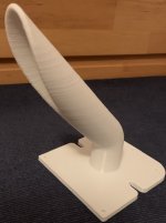
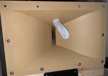
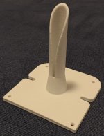
The 45 deg bent tube is just in the print.
The 45 deg bent tube is just in the print.
I'd love to sit down and talk with Tom Danley sometime about high frequency combiners. (Hey Tom, if you're reading this, PM me 😉
It's one of those things that's really intriguing. 75% of my Paraline experiments were disappointing. I had two or three that which were really promising.
The thing that keeps me going back to that well is that there were one or two which performed about as well as a conventional waveguide.
Now, if you read that, you might think "if the best you can do is something that's about as good as a normal waveguide, why would you pursue this?"
And the answer is that once you have a functional high frequency combiner, you can do some truly crazy stuff.
For instance, I was once measuring one of my Paralines, and noticed it was nearly 6dB louder than a conventional waveguide. And this seemed like it must be some kind of mistake, where's all that extra output coming from?
The answer is that horns raise efficiency by restricting output into a narrower beamwidth. So when you have a Paraline with a radiation of 90 x 10 degrees, it's going to be louder than a waveguide that measures 90x90.
As if that wasn't enough, you can now stack the Paralines, one on top of another. So you can get the output up even higher, AND the power handling.
But the Paraline is STILL a catch-22:
It's REALLY hard to get them to play past 15khz, even with a 3/4" tweeter. The Paraline is required to re-assembled the wavefront with basically zero pathlength errors to get to 20khz and that's hard to do. With a simply diffraction slot and a line of neodymium dome tweeters, you might be able to out-perform a Paraline.
It's a really tricky device to get perfect.
Note that the Sausalito Audio Works lens works in a similar fashion, and it's way easier to get those right.
hey pelanj - lost that short K-tube picture over a decade ago - here's a rough sketch going by those numbers - make any sense ? If a template were 1.5" wide at the exit, that would wrap about 1/3 of the way around the pipe.
can't remember exactly how it looked
for APT50 + APT3 adapter

can't remember exactly how it looked
for APT50 + APT3 adapter
The bent K-tube did print pretty well.
I was imagining an elliptical paraline with a MF and HF drivers at the focal points. I do not think that would work. Or maybe a half paraline-like device with the drivers on each flat surface and exiting to the side...
Freddi, thanks, now I understand, how the tube looks like. I might try that one day for a tweeter.
I really wish I could simulate the K-Tubes in ABEC to understand better hiw they work.
Attachments
it will be interesting to see if that mild bend works well or not vs say a bent horn.
I forgot to ask about the K-tube on top of your K15 Karlson - did you try a baffle at the
driver exit plane to reinforce the low end? - know your xover was high so might not
have much effect (?). If I get a new K built, I want to try that port shape like in your
K15.

I forgot to ask about the K-tube on top of your K15 Karlson - did you try a baffle at the
driver exit plane to reinforce the low end? - know your xover was high so might not
have much effect (?). If I get a new K built, I want to try that port shape like in your
K15.
Last edited:
Freddi, I did not play much with the K15, I am trying to make my main system sound better at the moment...
But I have some results with the bent K-Tube. And I think the results are quite interesting.
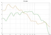
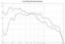
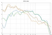
Again, my measurement techniques are far from perfect, but I tried to catch some trends in there. All plots are gated at ca 2.5 ms and 1/6 oct smoothed. The first one is on axis horizontally and roughly at the point of the K-Tube vertically at around 1 meter distance. The second one is at the same height but ca 20 degrees of axis horizontally. The third one is the two previous combined.
If I read that correctly, it seems to work and the bend does not have too much influence.
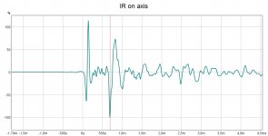
The IR shows that the mids are 0.65 ms delayed behind the HF (and I am not sure if the pulses are the same polarity or not). I will try to compensate the delay with DSP at some point.
As a conclusion, I would say that with a bit of EQ in the top end, this should work well and most probably even better with a smaller diameter tube. And it seems from all the measurements I made that in the HF, the K tube should be listened to almost on axis with the slot pointing up (or down ???).
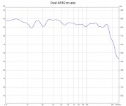
The last picture is the same drivers on ARB2 horns and physically aligned with passive XO as comparison.
But I have some results with the bent K-Tube. And I think the results are quite interesting.
Again, my measurement techniques are far from perfect, but I tried to catch some trends in there. All plots are gated at ca 2.5 ms and 1/6 oct smoothed. The first one is on axis horizontally and roughly at the point of the K-Tube vertically at around 1 meter distance. The second one is at the same height but ca 20 degrees of axis horizontally. The third one is the two previous combined.
If I read that correctly, it seems to work and the bend does not have too much influence.
The IR shows that the mids are 0.65 ms delayed behind the HF (and I am not sure if the pulses are the same polarity or not). I will try to compensate the delay with DSP at some point.
As a conclusion, I would say that with a bit of EQ in the top end, this should work well and most probably even better with a smaller diameter tube. And it seems from all the measurements I made that in the HF, the K tube should be listened to almost on axis with the slot pointing up (or down ???).
The last picture is the same drivers on ARB2 horns and physically aligned with passive XO as comparison.
Attachments
pretty good. What does the K-tube's constribution look like if the mic is pointed "straight down" the K-tube's long axis ? - that's where the HF is probably most extended. (?)
Actually, with this mechanical configuration, the mic is aligned "straight down" the long axis at 1 meter. It seems as the K-Tube has a constant-directivity like falling FR. Subjectively, there is enough HF in the room, so maybe not much boost would be needed. I am now not set up to run music through it and will not be for a while. One thing I need to try out is having a large XPS baffle around the horn flush with the front.
Comment from peanut gallery...
Mostly a lurker here. I find it amusing how much effort people worry about making sure they get enough output from a compression driver. Granted, usually the issue is to get them to play low enough. But output? They are ridiculously efficient (for home use). I mean, even "mosquito burner" wizard Danley's smaller offerings, even the SH50, or his bastard spawn the Yorkville Unity use a 1" CD for > 1000 Hz (approx.) And these are sized for club or auditorium use. Um, just how much HF do we need at home, guys?
Mostly a lurker here. I find it amusing how much effort people worry about making sure they get enough output from a compression driver. Granted, usually the issue is to get them to play low enough. But output? They are ridiculously efficient (for home use). I mean, even "mosquito burner" wizard Danley's smaller offerings, even the SH50, or his bastard spawn
the Yorkville Unity use a 1" CD for > 1000 Hz (approx.) And these are sized for club or auditorium use. Um, just how much HF do we need at home, guys?maybe enough to get a fairly "reasonably" believable snare drum rim shot "crack" and cymbal power on a close miced drumkit without too much thermal compression or driver overload - ?
It is not about dBs, it is about efficiency, so that I can run some sweet sounding SET amps with the horns. And this K-tube experiment is mostly about integrating the tweeter CD with the midrange as tightly as possible - since placing one on top of each other was OK, but not perfect. And as the last thing, it is fun to experiment🙂 Especially, the K-tube is kind of exotic and there is not much information about it...and I will most probably have a surprise ready from one very generous DiyAudio member...stay tuned🙂
Looks like your getting wide dispersion and more extended highs using the k-tube. So pretty successful!
Thanks to DonVK and Freddi, there are some ways for potential improvement. Discussed here: https://www.diyaudio.com/forums/mul...tube-1-compression-drivers-4.html#post6047971 DonVK simulated the K-Tube in ABEC.
Carl has experimented with shorter K-tube (3.5K up) and made K-tubes using laminated wood veneer in round and oval cross section for a more dead structure.
look at Karlson's "Open End Waveguide Antenna" patent
https://patentimages.storage.googleapis.com/0b/3f/f3/ba462c85c48ff9/US3445852.pdf
look at Karlson's "Open End Waveguide Antenna" patent
https://patentimages.storage.googleapis.com/0b/3f/f3/ba462c85c48ff9/US3445852.pdf
So one of the slimmer tubes is printed. I hope I calculated and measured right🙂
Now when the horn is drilled also from the other side, I will have three configurations to try out - that will be a mono test on my K15 clone - not only measuring, but also listening. Straight, bent and dual tubes with dual compression drivers. The K-Tubes are really interesting devices🙂
Now when the horn is drilled also from the other side, I will have three configurations to try out - that will be a mono test on my K15 clone - not only measuring, but also listening. Straight, bent and dual tubes with dual compression drivers. The K-Tubes are really interesting devices🙂
Attachments
- Home
- Loudspeakers
- Multi-Way
- Combining a 2" exit driver with a HF unit as a point source. Is it possible?