Can't comment on that sim, but you could experiment with the system in mono with the DSP you have to save on passive xover components.
If you have a rotating measurement jig you should take (full) horizontal and vertical measurements and checkout the xover in VituixCAD. Power response and good polar views will help you to tune the xover and sound.
Before cutting a hole to the mid horn you could try different positions and angles of the K-tube in front of the horn. If you hear significant difference in sound depending where the tube points at you just made a better speaker 😉 For this experiment you could questimate a crossover with DSP.
Anyway, trying out stuff before committing will teach you a lot and lead to better sounding design.
It is cool to see what you come up with and how it will sound!
Have fun!🙂
Yes, absolute levels are off by some 8-10 dB, you are right. I will try to reverse the resistors if there will be any difference. I think I tried both and there was not much of it. I imported also the measured impedance to XSim. Thanks for your help! Edit: Thanks go to both🙂 My measurements are not very professional, but I try🙂 I had the tube on top of the horns for a while, it did not catch up to the JBL2445 sensitivity and it was at the times with a passive crossover.
Last edited:
Stage one of this project will be printing mockups of the KTube part that will stick out inside the horn and I will try to measure the influence on the response, trying to get it as close to the throat as possible. This will be done in two sizes, one for 1" ID tube and one for 0.5" ID tube that would be suitable e.g for DE5. I will need to make a proper turn table.
What is the correct rotation point? Middle of the mouth, at the middle of the 2445
membrane, at the bug screen (end of the phase plug) or somewhere else?
What is the correct rotation point? Middle of the mouth, at the middle of the 2445
membrane, at the bug screen (end of the phase plug) or somewhere else?
Google search "vituixcad measurement preparations" document, all should be there. I think there is separate document for ARTA and for REW. With that guide you should be able to get good data in home environment.
Speaker frontpanel should be used for rotation center, so mouth in this case.
Turntable can be as simple as two pieces or ply with loose screw as center. Anything more slippery than ply will rotate easier, melamine surface (cheap furniture panels) for example. Or put some marbles on a round groove between the panels. It is all good as long as the DUT and mic stay in place when you turn
Last edited:
I used a speaker stand until now. But I need something more heavy duty for the horns. As I see it, the turntable should have a straight front or I need to make sime fixture so I do not get reflections.
You can put the turntable on the floor and speaker stand on top of it. But yeah, the turntable quickly gets pretty large.. I have speaker about one meter high and weird shape, almost meter wide, weights a lot. really difficult to measure. Butchered a dolly cart, round ply taped to the floor undernetaath providing the angle scale and center point. Then ratchet strap the speaker on a makeshift stand on the dolly, use long steel bar as center pin, attached to the dolly, and another to point the angle. Pretty easy to turn around but easily a centimeter or two of since the jig isn't very stable. But, havent figured out better rig yet 😀 I think it would be easier to move the mic 🙂
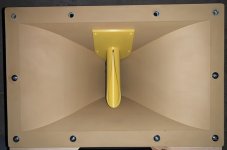
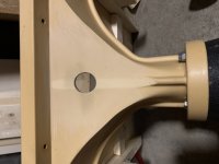
There are not too many options of how to install the K-tube of this size. Of course, the mounting plate will be outside and the foam is just a support for taking pictures. It seems when I place the tube as close to the mouth as possible to fit the HF driver, it should be just about the right length and angle based on previous experience. It will be some fun to drill the hole properly...
Attachments
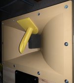

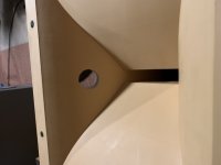
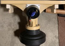
Beyma CP385/Nd, since that is what I have at the moment and it is really good. And JBL2445 for midrange. A hole is drilled and new K-Tube with updated dimensions is being printed🙂 Drilling the hole was quite easy with a 32 mm hole saw. The material is easy to work on.
Attachments
Last edited:
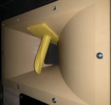
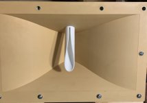
So the K-Tube is printed and installed in the horn. I could not resist and made some measurements on axis. I will not show them yet, they make exactly zero sense to me. I need to do the measurements outside, inside my cluttered workshop it seems not to work. Subjectively, the tube seems to do something and the HF in the far field is extended, when playing both together. The tube inside the horn does not seem to influence the mid driver response much if at all. The tube response is falling at a similar rate as the mid, but higher. That would indicate that the chosen angle is way off...I hope I will have a chance to measure outside tomorrow. Unfortunately, a different angle will be very difficult to do.
Attachments
Last edited:
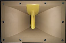
Yep, wrong orientation - I did measure some more and that proved the fact. The Faerber Acoustic speaker has it right. Back to the drawing board🙂 The bad news is that there is not much space around the horn to fit in the Beyma. So most probably I will need to get a smaller driver or finally order a pair of VIFA NE19 tweeters. The 2445s are sensitive as hell and even the Beymas need something like 4 dB boost in voltage (they are 8 ohm nominal, 2445s are 16 ohm nominal).
That also means it will most probably not be possible to align the K-Tube in vertical position fully - as it is the case of the Faeber speaker.
That also means it will most probably not be possible to align the K-Tube in vertical position fully - as it is the case of the Faeber speaker.
I thought about bending it, I think I should be able to do it in 3D and the printer would definitely print it, maybe even in one part. But I am afraid of introducing interference from the bend. How about making a reflector instead? So the bend would be sharp?
The easiest way will be to model both and print. Definitely easier than drilling the horn at a steeper angle🙂 The K-Tube of this size looks quite good above some 4 kHz. Verically it is almost flat within ca 30 - 40 degrees. Horizontally, the dispersion is somewhat wider, acceptable almost to some 60 degrees. These are all estimates based on some measurements and my ears🙂
The easiest way will be to model both and print. Definitely easier than drilling the horn at a steeper angle🙂 The K-Tube of this size looks quite good above some 4 kHz. Verically it is almost flat within ca 30 - 40 degrees. Horizontally, the dispersion is somewhat wider, acceptable almost to some 60 degrees. These are all estimates based on some measurements and my ears🙂
Karlson's earliest X15 speaker was from 1965 and had a 3" cone tweeter in a mini-klam as tweeter. I'm guessing the next year introduced the K-tube. This is one which I own with a 1.875" diameter K-tube. Another X15 seen had what looked like a 1.25" diameter tube (probably smoother). I bought this pair with the K-tube sawed out by the previous owner.
X15 was 28" high by 19.375" wide by 13.75" deep and the K-tube was mounted on the lower reflector panel, tilting down from horizontal by 12 degrees.
I have an 18" K-type cabinet which can run an internal K-tube - its a great way to make a speaker.
previous owner pictures


X15 was 28" high by 19.375" wide by 13.75" deep and the K-tube was mounted on the lower reflector panel, tilting down from horizontal by 12 degrees.
I have an 18" K-type cabinet which can run an internal K-tube - its a great way to make a speaker.
previous owner pictures
Freddi, could you please measure what is the approximate angle of the KTube down from horizontal? Or what is the optimal angle for the K-Tube from your experience?
I tried to measure outside. The response is more bumpy than inside, most probably due to wind and noise around. I will try to make some meaningful conclusion later.
when I use it on top of a Karlson, typically tilted like the baffle angle
Karlson's X15 had its 7.25" long tilted down 12 degrees
https://i.imgur.com/qMFgzEL.jpg
Carl - interpretation of X15 - maybe 35 degrees down ?
https://i.imgur.com/rLYvuEC.jpg
My K18 tube on top 30 degrees down - much less when tube is in
the front chamber
https://i.imgur.com/eL3agYf.jpg
Wolf von Langa - steep angle
https://i.pinimg.com/564x/d2/05/f2/d205f23f495d208da92f2c2d41fe000a.jpg
IG81 Transylvania Power "The Tube" 30 degrees up
http://i.imgur.com/w3rBDyR.jpg
Eight inch coupler with tube on top 30 up
http://i.imgur.com/aVgBwJ7.jpg
So my angle is way way off. I will try to bend the tube and have it pointing max. 15 degrees down. Mine is almost 65 degrees IIRC.
Just try with a small horn above the JBL clone horn first. At 8Khz XO maybe things will go smooth.. something like Beyma CP09.
- Home
- Loudspeakers
- Multi-Way
- Combining a 2" exit driver with a HF unit as a point source. Is it possible?