During the last days, I was reading a lot of posts about paraline, combining compression drivers, directional arrays, Unity/Synergy horns and so on.
I wonder if there is a way to integrate for example JBL2445 or similar driver that is lacking in the HF with some sort of device to have point source behavior at a relatively short distance - say 1.5 m and further. If possible, it would be nice not to use digital delay between the two units, but can be used if necessary. I would like to crossover the JBL2445 at around 600 Hz
The best I have tested so far was to use two identical horns for the JBL2445 and HF compression driver with an adapter to match the time of flight to the listening position and to integrate well at least in the horizontal plane. This is as good as I can do. Would it be worth trying to pursue alternative ways?
The tools available include a 3D printer and DSP for delays, crossover and EQ.
I see some potential ways to try out.
1) use two paralines to combine the 2" and HF drivers into a conical horn. One shorter, one longer, maybe trying to steer the wavefronts a bit towards each other. The path lengths could be matched by using phase plugs going into the throat of the 2445 and HF driver to keep the conical expansion as close to the throat as possible, the HF driver would include an adapter for the correct distance.
2) use one paraline with both drivers - matching the pathlengths mechanically should be possible as well.
3) Use Danley throat combiner-like device to use both in one horn. Or any other similar device to make the drivers combine into one horn. The HF driver can be again made to have a 2" exit and same distance from membrane to throat as the 2445
4) "Inverted" Unity - to have the 2" driver in the center and multiple HF feeding into the horn. Most probably a very bad idea.
5) Place a small HF with horn inside the MF horn hidden in a phase plug like device and use delay to match the path lenghts.
6) Similar to 3, but Unity style - the 2445 would be fed to the horn through the side of the HF throat adapter at the correct place.
7) Anything else? Including that to have two identical horns is as good as it can get? And that a conventional unity is better in this regard...I would really like to use the 2445s.
All of above should be possible to at least prototype with a 3D printer, so any guidelines would be appreciated - e.g. rule out the really bad ideas. The 2445 can be equalized up to some 8 kHz without sounding too bad. The desired coverage pattern would be 90Hx60V or smaller, as low as possible. In this case, space occupied by the horn(s) is not a concern.
Just putting a small horn in the mouth of the larger horn is a common solution (no attempt to make it a phase plug etc.). You see small horns at the edge of larger horn mouths from Funktion 1 and Pioneer.
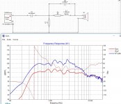
The 2445j should be able to get to 20kHz with eq but is in breakup (see plane wave tube results) which may be the source of the bad sound. You can get Be diaphrams which solve this but they are very expensive. You could add a diffraction slot to your horn if the dispersion is poor.
The 2445j should be able to get to 20kHz with eq but is in breakup (see plane wave tube results) which may be the source of the bad sound. You can get Be diaphrams which solve this but they are very expensive. You could add a diffraction slot to your horn if the dispersion is poor.
Are you aware of the coaxial compression drivers like BMS Coaxial Compression Drivers and rather recent B&C DCX series? B&C Speakers
5) Horn inside a horn could work, but it is a worse compromise to coaxial driver I think. HF horn has to be certain size to have desired directivity at crossover frequency. Now the MF horn has to play to the crossover frequency as well but the HF horn is on the way (large obstacle). Either of the two must have some anomalies that wouldn't exist if the HF horn wasn't inside the MF horn.
I think it is really hard if not impossible to outperform a Multiple Entry Horn (unity/synergy) speaker if point source is desired. Coaxial compression driver or some larger coaxial driver would be easier and cheaper to implement to achieve point source.
I think it is not a bad compromise to have a crossover at ~1-3kHz like with Patric Bateman latest projects have. So yeah drivers like 2445 are more suitable for larger rooms than near field listening for the reason it is hard to add tweeter and have a point source. Gotta decide some design goals and then live with the compromises 😉
kipman725: Yes, it can be equalized, but it sounds not too good in the highest range. Maybe I should try to use it as high as I can accept and then use a super tweeter that would not be coherent anyway. There is a diffraction slot in my horn and the horizontal dispersion is actually acceptable when I use the second horn for HF - but the vertical is not too good for the combination of the two since they are both large (2380 knockoffs at the moment). Berylium is out of question, I can buy a nice set of new 1.4" drivers for that price.
tmuikku: Yes, but the point is I already have and use the 2445s🙂 I built the UICW project by PB and yes, it is great, but still have had not much time to test and listen long enough. The 2445s have some strong points and I would like to keep using them. I will probably try some experiments and if that does not work, I will try to sell them with a bleeding heart, since I will not have any use for them anymore.
tmuikku: Yes, but the point is I already have and use the 2445s🙂 I built the UICW project by PB and yes, it is great, but still have had not much time to test and listen long enough. The 2445s have some strong points and I would like to keep using them. I will probably try some experiments and if that does not work, I will try to sell them with a bleeding heart, since I will not have any use for them anymore.
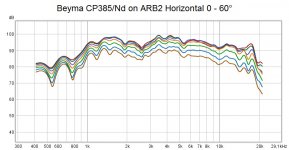
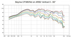
Here are some polar measurements (very crude, in room, heavily gated) with the HF driver with adaptor on the same horn as the JBL uses. The adaptor is just a conical tube and the seal is not perfect, so there is room for improvement. If this could be combined in the same horn with the 2445, I would be happy. So I will try out a few things and report back if anything worked.
Attachments
An externally hosted image should be here but it was not working when we last tested it.
XY Series XY-3B | PIONEERPROAUDIO this is the pioneer, kind of a compromise between a centre mounted horn and a horn further away.
Little off topic, about this pionner, i just seen this : YouTube where we can see the midrange compression plug in detail at 2:49 and 1:44. I would be really interest in seen other view of this piece. It seems that it's a radial phase plug, with a secondary outside path that seems curvated, should it be to compensate for cone depth difference between middle of the cone and outside of the cone ? or i am dreaming about something too complexe ? I've never seen this, and i'm actually learning 3d modelling exactly to test this kind of phase plug (if i'm right on what i see in the video)...
kipman725: Yes, that is also one of the things that came to my mind when you said a HF horn can be placed at the lip of the midrange horn - the HF horn could be integrated into the midrange horn. I am not sure I can succeed with this, but I have two spare horns and each costs only 10 Eur, so I can do some drilling and cutting without a big loss. A 3D printed insert would be made to fit and glued to the horn.
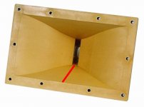
For the paraline idea, I have attached a picture of the horn. If the paraline would bend the wavefront (and it should be able to do that), it could be also an option.
Or I imagine making a tap into the diffraction slot with a small compression driver - most probably not the best idea, but might work.
Attachments
Stick a K-Tube there, you got them printed if I remember? Might work well and you'll get weird polars what ever you do anyway. Not sure if there is any problem with such high frequencies though, anything that works for you is fine 🙂
Vorschau HIGH END 2012 - Messebericht HIGH END 2011 - Faerber Acoustics - Frank-Landmesser.de
A karson tube tweeter through a mid horn 🙂
A karson tube tweeter through a mid horn 🙂
It could be that the reason the large comp sounds bad even when EQ'd is the diffraction slot in your current horn. I haven't personally listened to horns with such 'hard' diffraction features but other people complain of 'frying eggs' noise especially at high output. Have you tried it on a more modern horn design? perhaps biradial?
Yes, I completely forgot about them! Thanks for reminding, that should work🙂 At least somehow - I will need to print a new pair with longer part without a the slot, so that the slot starts right above the horn wall.
I think it sounds bad because it needs really large boost for the HF. I have no problem with the sound of a Beyma CP385/Nd on the same horn.
I think it sounds bad because it needs really large boost for the HF. I have no problem with the sound of a Beyma CP385/Nd on the same horn.
What kind of processing are you using to apply the boost? perhaps you loose too much dynamic range or have clipping or numerical instability. There is nothing intrinsically wrong with large boosts but a lot can go wrong, for example using IIR filters the coefficients need to have a high numerical precision.
This is one of the reasons I use a passive crossover on my comps as I can include most of the EQ in that crossover so don't need large boosts in the digital domain and improve dynamic range.
The boost is via Thomann DSP 4x4, the output had still tons of headroom - but maybe the result would be better with passive attenuation instead. I will definitely need to try that, too.
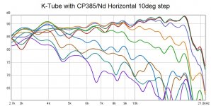
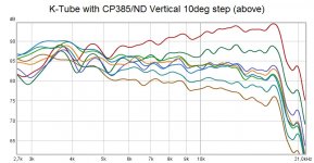
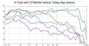
I revisited my K-Tube measurements and I shortened the window to take out the first reflection. Above means the part without the slot. I do not think I can resist sticking the K-Tube into the horn now🙂 The main point as I see it is bringing the output closer in the vertical direction, which would be my goal.
I revisited my K-Tube measurements and I shortened the window to take out the first reflection. Above means the part without the slot. I do not think I can resist sticking the K-Tube into the horn now🙂 The main point as I see it is bringing the output closer in the vertical direction, which would be my goal.
Attachments
The Thomann DSP is a quite low cost unit I would guess it uses fixed point processing so I would try a basic passive network to equalise and then do the 'fine tuning' in the DSP. Even if its floating point (which avoids the problem of accidentally digital clipping in the processing pipeline) its probably only 32 bit which isn't sufficient precision for high Q IIR filters. If you open it up you will be able to see the DSP chip it uses and the data sheet you should be able to check this. You could also try as a quick fix to split your overall EQ into half boost and half cut and/or trying to use low Q PEQs.
The way you could actually test your DSP is to put in the EQ you want and measure the response using REW, comparing it to what you expect to get. They should exactly match if they don't you have issues!
I'm using a Symetrix Symnet 8x8 DSP, they are sometimes available very cheaply and have a 40 bit floating point data representation (enough for 24bit data), they use multiple xilinx spartan 6 FPGAs for processing the audio data.
I revisited my K-Tube measurements and I shortened the window to take out the first reflection. Above means the part without the slot. I do not think I can resist sticking the K-Tube into the horn now🙂 The main point as I see it is bringing the output closer in the vertical direction, which would be my goal.
Looks great! the K-tube should also have minimal interaction if put in carefully, I would keep it away from the diffraction slot.
I was digging through some old measurements and now I know why that actually sounded so horribly...it was the microphone which had bad HF response - and when equalized flat, there was just too much breakup treble at least by some 6 dB or maybe even more. The Thomann DSP main chip type is scraped out for some reason. And it was also another horn which was not as flat as the ARB-2. I can definitely drill a hole into one of the horns and compare the result. I will try two K-Tubes - one shorter about the size I have now and one longer that would time align the drivers - which will require a longer tube - which in turn can screw up the response. In the picture on the previous page, it actually seems they are trying to align the HF driver with the midrange.
- Home
- Loudspeakers
- Multi-Way
- Combining a 2" exit driver with a HF unit as a point source. Is it possible?