That seems to be a different one. I found this https://www.diyaudio.com/community/attachments/8pe21-tapped-horn-jpg.133253/
You mean published TS parameters for the 8PE21? The grey one looks better - do I understand it correctly that I get the black line with real drivers? Or the grey line with real drivers? I will try to run the simulation myself as well.
No, the shadow if the published specs are most correct. That said, it just 'dawned' on me (the caffeine finally 'kicked' in) that back then HR apparently wasn't programmed to sum driver specs, so he modded them to get the most correct response, i.e. don't use his specs under the assumption that they are measured.
Attached 'updated'/'corrected' sim; note the 3 ohm series resistance and power based on a 16 ohm load, making me wonder if it was tube driven..............
Attached 'updated'/'corrected' sim; note the 3 ohm series resistance and power based on a 16 ohm load, making me wonder if it was tube driven..............
Attachments
Last edited:

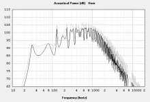
That dual 8PE21 horn is really a nice design - pretty small for what it can do. I shortened it to 0.8 of original length and got this (black, grey is the original):

The motivation is that I was after 35 - 40 Hz at the low end in a compact box. With the smaller one I get almost 112 dB/m at 35 V still below XVar.
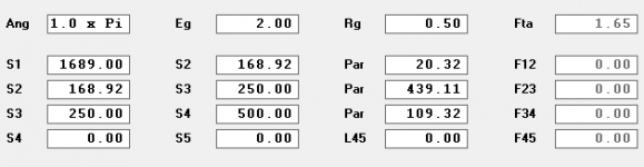
The net volume is 90 l, but I yet have to figure out how to place the drivers and how to fold it. The instructions mentioned in the thread say they are placed like in the SPUD (i.e. one reversed if I understand it correctly) and the folding should be like Volvotreters W6 horn - I checked the plans but cannot imagine fitting a reversed driver there.
My modified HR record is also attached.
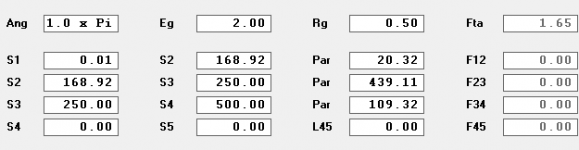
I was however surprised by one thing. There is a difference between serial and parallel wiring for the two drivers - grey is series, black is parallel. Until now I thought this would not matter if connected series or parallel.

The motivation is that I was after 35 - 40 Hz at the low end in a compact box. With the smaller one I get almost 112 dB/m at 35 V still below XVar.
The net volume is 90 l, but I yet have to figure out how to place the drivers and how to fold it. The instructions mentioned in the thread say they are placed like in the SPUD (i.e. one reversed if I understand it correctly) and the folding should be like Volvotreters W6 horn - I checked the plans but cannot imagine fitting a reversed driver there.
My modified HR record is also attached.
I was however surprised by one thing. There is a difference between serial and parallel wiring for the two drivers - grey is series, black is parallel. Until now I thought this would not matter if connected series or parallel.
Attachments
Hmm, ATM my understanding is that we can't mount them as simmed, but if true, then at this late date I'm guessing we couldn't sim it correctly with HR's original TH designer, so FWIW, etc., here's an example of my way for expanding, contracting termination (low pass filter):
Attachments
Right, more current = more distortion, so either use the lossy Le or 'power compression' option if long term average power is > 'x' % of its power rating normally arrived at empirically by DIYers.
I did play a bit with simulations yesterday, swapping BC 8PE21 and Fane Sovereign 8-225 and I have a few observations/questions.
1. Is it correct, that the lower the Qts (or Qes?) of the driver, the smaller volume/CSA the horn needs to be flat.
2. If the volume/CSA is too low, the low end suffers with a peak
3. If the volume/CSA is too large, I get peaks on both ends of the pass band
4. I can shape the response somehow by adding offset of one or other end.
I will try to modify the design so that it is actually buildable and uses only one 8PE21. It seems it can be squeezed into a really small box, so it could be used in pairs.
I was not able to come up with anything meaningful. I still like the idea of using two 8PE21s in a tapped horn since the box needs relatively low volume compared to other drivers. Both speakers would have to be placed along the horn path (not side by side), so I wonder how to simulate that with HornResp.
I can think of two options.
a) use the center line between the woofers as the driver position
b) simulate both positions and add up the responses
Which of these would be closer to reality? Or is there any better way?
I can think of two options.
a) use the center line between the woofers as the driver position
b) simulate both positions and add up the responses
Which of these would be closer to reality? Or is there any better way?
David McBean has answered this over at the hornresp thread. Why not ask there? He's very helpful and generous with his knowledge.
Thanks for the tip. A quick search revealed it is answered in this post: https://www.diyaudio.com/community/threads/hornresp.119854/post-3682531 - so I will just use the center line. I only need to figure out how and where to fit the woofers, ideally one with reversed mounting.
Both speakers would have to be placed along the horn path (not side by side
Why you can't use them side by side?
- Home
- Loudspeakers
- Subwoofers
- Collaborative Tapped horn project