Thanks Oliver, that does look like the stuff in the commercial tapped horns, but I'm hoping to avoid a trip to the city for this. I think I can find some old blankets to rip up that might have batting if I need to.
Thanks again, jbell. That stuff does look like what I have, and I'm not particularly concerned about it soaking up too much, I'm only worried about the apparent size of my throat once it's in there.
I'm probably not going to line all 4 sides of the entire path anyway, it's too much work and doing two opposite sides should be almost as good. I can probably separate this underlay stuff into two 1/4 inch layers too and then only do 2 sides, I'll play with it and see what feels right, fibreglass vs thin layers of wool underlay vs batting (assuming I can find some).
GM said:
It's a design variable that the manufacturer specs. FWIW, I use the time honored 1" acoustic fiberglass insulation that historically could be found in bulk at big box building suppliers, so I assume there's Canadian equivalents: http://www.owenscorning.com/around/sound/commercial_acoustics/snd-attenuationbatts.asp
GM
You guys answered while I was typing, so I guess that one vote for fibreglass and one for batting. Thanks GM and littlemike.
Cheap easy source of acoustical fiberglass...
is flexi ceiling acoustic tiles 2'X4' in size fiber thickness is about 5/8" thick The white face material is pvc and peals off of the fiberglass easily if you have an application where you want both sides exposed. In a cabinet for wall lineing no need to remove the film just place it toward the cabinet wall. You can purchase much bette acoustical fiberglass from companies such as Corning 701 or 703 I think you would need to check has wider band absorption but cost a lot more. This stuff works well and is dirt cheap and easy to find at home and building supply stores.
is flexi ceiling acoustic tiles 2'X4' in size fiber thickness is about 5/8" thick The white face material is pvc and peals off of the fiberglass easily if you have an application where you want both sides exposed. In a cabinet for wall lineing no need to remove the film just place it toward the cabinet wall. You can purchase much bette acoustical fiberglass from companies such as Corning 701 or 703 I think you would need to check has wider band absorption but cost a lot more. This stuff works well and is dirt cheap and easy to find at home and building supply stores.
Guys,
many thanks for all your answers.
As often the devil seems to be in the details.
Unfortunately, I only do have a short week-end ahead of me, but I will definitely try air-tightening the thing better and augmenting the driver opening... I will probably end up gluing everything together which will make experiments more difficult but at the end of the day, it is just 20€ of wood...
I will keep you posted with my progress, most probably early next week now.
Re : Ceiling tile
It's easier to use the white side of the tile as a backer to glue the fiber glass to the side walls. Smoother and allready well glued to the fiberglass. I use adhesive to glue the panel to the side walls. My favorite is water based wall tile adhesive. It also really deadens the box walls.
Mark
It's easier to use the white side of the tile as a backer to glue the fiber glass to the side walls. Smoother and allready well glued to the fiberglass. I use adhesive to glue the panel to the side walls. My favorite is water based wall tile adhesive. It also really deadens the box walls.
Mark
Re: Re: reactance annulled AFAIK TH ?
It's not directly related to the free air resonance of the driver, you're adjusting the total compliance of (driver+rear chamber) to resonate with the total mass of (driver+air load) and cancel out the reactive part of the horn acoustic impedance at the quarter-wave resonant frequency and thus maximise the output.
You could have a driver with a 1Hz resonant frequency and this would still work -- in which case all the stiffness comes from the small rear chamber -- or a driver with a high resonant frequency well above the horn cutoff and no rear chamber, in other words a tapped horn.
Tom's latest 38Hz tapped horn (the TH-212) uses 2 Faital Pro 12HP1020 drivers which have Fs=55Hz, unusually high for long-throw 12" drivers which is one reason they work very well.
Ian
GM said:
As it pertains to a TH, pardon me for declining as I believe it's the key to getting the amount of acoustic power some DSL products measure Vs what folks sim/measure when they try to 'clone' some of them. Again though, I have no 'insider' knowledge of any of DSL's TH designs, so this is strictly a personal opinion based on what I've learned in my 'adventures' in horn design.
Regardless, until I can confirm for myself it's just a theory on my part, though Prof. Leach's math and Hornresp sims gives me high hopes. Also, I use the term 'reactance annulled' because it's the only way I can think of to describe the design routine, so it may not be the most technically correct, but unless someone can convince me that a TH can't be reactance annulled or at least close to it I'm going to continue to describe it as such.
Reactance annulling a FLH though is simply enclosing the rear of the driver with an acoustic compliance that offsets the horn's acoustic mass loading, i.e. if the driver has a free air resonance of 50 Hz and the horn lowers it to 25 Hz, then a high Q rear chamber is added to push the system resonance back up to 50 Hz.
GM
It's not directly related to the free air resonance of the driver, you're adjusting the total compliance of (driver+rear chamber) to resonate with the total mass of (driver+air load) and cancel out the reactive part of the horn acoustic impedance at the quarter-wave resonant frequency and thus maximise the output.
You could have a driver with a 1Hz resonant frequency and this would still work -- in which case all the stiffness comes from the small rear chamber -- or a driver with a high resonant frequency well above the horn cutoff and no rear chamber, in other words a tapped horn.
Tom's latest 38Hz tapped horn (the TH-212) uses 2 Faital Pro 12HP1020 drivers which have Fs=55Hz, unusually high for long-throw 12" drivers which is one reason they work very well.
Ian
Re: Re : Ceiling tile
But don't you have to account for the lost Vb due to the backer's high density? Not a big deal in a large cab, but some of these THs are tiny in their early expansions. Regardless, seems to me Bob Brines does this in his TL, MLTL designs and it seems to work well.
GM
mwmkravchenko said:It's easier to use the white side of the tile as a backer to glue the fiber glass to the side walls.
But don't you have to account for the lost Vb due to the backer's high density? Not a big deal in a large cab, but some of these THs are tiny in their early expansions. Regardless, seems to me Bob Brines does this in his TL, MLTL designs and it seems to work well.
GM
tb46 said:
Just playing with the TD10H in Hornresp it looks like any number of reasonable alignments can be found with an acceptable (to me about +- 3dB) amount of ripple. This particular driver seems to respond well to a series inductor (Le add 7mH, Re add 0.35Ohm). And, if the enclosure width is a problem, the use of multiple drivers seems to be the way to go. I'll attach the Hornresp input screen for a dual with a similar volume to your design, just something to get you started.
Thanks for that. Unfortunately 2 drivers per cab puts cost out of reach, though that is a sexy flat curve.
I tried adding inductor to my single driver design and it allowed me to bring the CR down to 3:1 without sending things too crazy. Are there any general rules for adding inductors? (Type, value of Le, DCR, power handling etc, cost?)
GM said:
According to Tom Danley, a ~3:1 CR is pretty much the limit for prosound apps.....
That said, none of the TH designs others have posted so far are reactance annulled AFAIK, or at least enough to allow a high CR at high excursion without the driver going non-linear....
Thanks, in this context is reactance annulled required for a CR of 3:1? (Not sure what you mean by high CR)
I hope to use these both in the house (multi sub ala geddes) and as a small high quality PA rig.
🙂
Re: Re: Re: reactance annulled AFAIK TH ?
Yes, and no, it depends on the alignment. That said, I was writing these responses during breaks in yard work and didn't proof them as I should have. My bad. Instead of driver Fs I should have said system Fs.
GM
iand said:
It's not directly related to the free air resonance of the driver.......
Yes, and no, it depends on the alignment. That said, I was writing these responses during breaks in yard work and didn't proof them as I should have. My bad. Instead of driver Fs I should have said system Fs.
GM
fb said:
Thanks, in this context is reactance annulled required for a CR of 3:1? (Not sure what you mean by high CR).........
That's my understanding for a prosound app if high excursion/power is used rather than multiple subs to keep them moderate. For a typical cone driver in a prosound app, I consider >2:1 CR as high in a TH.
GM
Hi,
Is there any other successfull tapped horn alignment here in collaborative thread that comes close to labhorn performance other than jbell's 2'x3'x4' 3015LF ?
Is there any other successfull tapped horn alignment here in collaborative thread that comes close to labhorn performance other than jbell's 2'x3'x4' 3015LF ?
Post #3088
Hi fb,
The general rules for using an inductor with a tapped horn are: enter resistance value into Hornresp under Rg, enter inductance by adding to Le, and "fiddle" with the values until you find a SPL curve you find acceptable. As to the inductor, you are looking for minimum resistance for a given inductance to reduce the power dissipation. I like this Parts-Express part:
http://www.parts-express.com/erse-16-gauge-inductors.cfm
The power handling capacity is definitely something to consider. I would keep in mind, that according to Tom Danley neither Hornresp nor AkAbak show all the internal losses, and that some model response peaks disappear in real life, so things may be better than initially modeled. While talking about money, take a look at the CSS SDX10, it lists for $139.– and has an impressive Xmax of 18.4mm.
Regards,
Re Re RE Ceiling tile
Hi GM!
I can't say for certain that the space occupied by the fiber glass would account for a loss in the horns apparent throat volume. Looking up the STC rating of the normal 1/2 " fiberglass you get from .5 to .7 the number 1 being totally absorbent. This is frequency dependent as an absorptive layer starts to work at 1/4 wavelength of the thickness of the absorptive panel. If the panel is 1/2" thick it will begin to work around 3.4khz and up. Looking at a normal enclosure that we add fill to then the actual end result is an apparent net gain in the acoustical size of the enclosure. And if applied correctly as I think it is done in the Danley subs it reduces the high frequency peaking that we are all simulating and some are measuring. It may even be acoustically transparent over the passband we want out of a sub.
But don't you have to account for the lost Vb due to the backer's high density? Not a big deal in a large cab, but some of these THs are tiny in their early expansions. Regardless, seems to me Bob Brines does this in his TL, MLTL designs and it seems to work well.
Hi GM!
I can't say for certain that the space occupied by the fiber glass would account for a loss in the horns apparent throat volume. Looking up the STC rating of the normal 1/2 " fiberglass you get from .5 to .7 the number 1 being totally absorbent. This is frequency dependent as an absorptive layer starts to work at 1/4 wavelength of the thickness of the absorptive panel. If the panel is 1/2" thick it will begin to work around 3.4khz and up. Looking at a normal enclosure that we add fill to then the actual end result is an apparent net gain in the acoustical size of the enclosure. And if applied correctly as I think it is done in the Danley subs it reduces the high frequency peaking that we are all simulating and some are measuring. It may even be acoustically transparent over the passband we want out of a sub.
Greets!
Assuming we're talking about the same kind of panels, others have told me there's some volume loss, not gain, as would be the case with fiberglass insulation, polyfil, etc. as long as it's not too densely packed of course. I assume the batting DSL uses falls in this category.
Yes, from the various plots it appears there's considerable initial damping, like in a high gain pipe horn.
GM
Re: Post #3056, Hornresp throat chamber
I believe you've done everything correct with your input parameters. What happened to my first tapped horn was the bass went deeper and louder once I opened up the woofer hole. I never measured the difference, but it was easy enough to hear. However, this doesn't explain what's going on in this case. I'm at a loss to suggest what might be the problem. The woofer opening was just something that was easy to see. I hope he can figure out what's happening. All my tapped horns have put a grin on my face.
Rgs, JLH
tb46 said:Hi just_a_guy:
I'll attach the Hornresp input screen, Ap and Lpt define the opening, and Vtc and Atc are the throat chamber. I just took a stab at the values to see if there was any large change.
Regards,
I believe you've done everything correct with your input parameters. What happened to my first tapped horn was the bass went deeper and louder once I opened up the woofer hole. I never measured the difference, but it was easy enough to hear. However, this doesn't explain what's going on in this case. I'm at a loss to suggest what might be the problem. The woofer opening was just something that was easy to see. I hope he can figure out what's happening. All my tapped horns have put a grin on my face.
Rgs, JLH
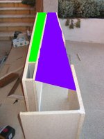
I think I know what is going on here now. I ended up splitting up the 259cm length and making this a 4 segment tapped horn. I was then able to use the tapped horn wizard and duplicate the measured response. The problem appears to be the flare rate in the throat is slower than what is in the model. This is the green area in the attached picture below. Also, the purple area has too fast of a flare rate, (i.e. it expands too fast). Lastly, it appears that the L34 segment is not 48cm long, but a bit too short. This could just be a case of not building something close enough to what was simulated.
Attachments
fb_TH problems_JLH Post #3095/3096
Hi JLH,
I'm also not certain about the dimensions, that's why I asked jm_kzo in Post #3053 to check all dimensions. I still have not seen a drawing of the actual enclosure, and I cannot get close enough just looking at the picture. I like your rendition of the box.
Even at the very long wavelength in the passband, the transition between the driver/compression chamber and the horn has to have some kind of an influence, I wonder if that's what you heard. Screamerusa seems to indicate in the PA-TH thread that even small changes in the throat area make a very measurable difference.
Regards,
I've found the differences between parabolic (what I typically build) and conic expansions causes some issues in translating from hornresp to wood. (as don has pointed out in the past)
I typically find that the more segments that I can model in hornresp. (1 segment per fold in FLH for example) The closer what I build is to hornresp's prediction. Usually I have to export from horn resp and check areas along the path and adjust my cabinet dimensions to try to stay close to conic.
David: any possibility of getting a parabolic expansion added to hornresp? That way we have a straight forward method of translating what's sim'd to a cabinet design?
http://www.diyaudio.com/forums/showthread.php?postid=1605620#post1605620
Parabolic?! In a prosound app seems like you'd want the max gain practical for a given bulk, which is the opposite of parabolic.
GM
GM
I had the same type of issue when transporting a conic design from hornresp into cad. (I didn't actually do the cad work, I'm not nearly smart enough - I gave the cad man the plan and post 1490 and volvotreter's folding scheme and a drawing of my peculiar folding and told him to go at it.)
Unfolded, with the same mouth and throat size, cad and hornresp disagree on S2 and S3. Cad shows S2 and S3 to have a slightly larger cross sectional area than hornresp in the middle of the line. That was bothering me, as I've spent dozens if not hundreds of hours on the design to that point. I told the cad man to just keep going or the folding would have taken too long.
He continued the folding with volvotreter's spreadsheet as a guide, which IIRC is known to have a small percentage of error as well. I worked with him to try to fudge the numbers back closer to the hornresp inputs (thinner through the middle) but without working it out from the beginning by hand (which I really did not want to do) the results will be unpredictable until measured I guess.
My peculiar folding (to eliminate wasted space) adds another percentage of error, unless accounted for in the beginning, which of course it wasn't.
Add a couple millimeters error here and there in the actual construction (I'm not a woodworker by trade, hardly even a woodworker by hobby).
The lining apparently is going to add another percentage of error in cross sectional area and a smoothing of response not predicted by hornresp.
In the end, I probably won't even post a hornresp input screen with my project report, since it will be impossible to correlate the inputs to the finished product anyway after so many compound errors and response smoothing from the lining. I'll probably include the cad drawing only, that will be the closest thing to the finished product except for woodworking errors.
It's easy to screw up a design in translation, especially with mulitple folds. I tried at least to stay as close as possible to the original intent (of my own design) but wasn't really able to. These are all only small(ish) errors but they add up, so we'll have to see.
- Home
- Loudspeakers
- Subwoofers
- Collaborative Tapped horn project