Re: Post #3056, Hornresp throat chamber
Yeah, sounds reasonable guys, thanks for saving me from stupidity once again.
As far as I'm concerned, if it is even suspected that there might possibly be a single air leak anywhere the whole thing should be sealed up tight with silicone inside and out.
tb46 said:...Ap and Lpt define the opening, and Vtc and Atc are the throat chamber.
Regards,
MaVo said:
I think you can do this with the front chamber function in hornresp. ...Also, it should have nearly no influence to make the opening smaller... It has only influence on the high frequencies.
Yeah, sounds reasonable guys, thanks for saving me from stupidity once again.
About the malfunctioning TH: You can find harmfull leaks easily if you play some loud deep sine tone and then move your hand around every spot that could have a leak. You will notice the air blowing out of the hole. Check especially in the vicinity of the driver.
As far as I'm concerned, if it is even suspected that there might possibly be a single air leak anywhere the whole thing should be sealed up tight with silicone inside and out.
jm_kzo said:
Hi littlemike,
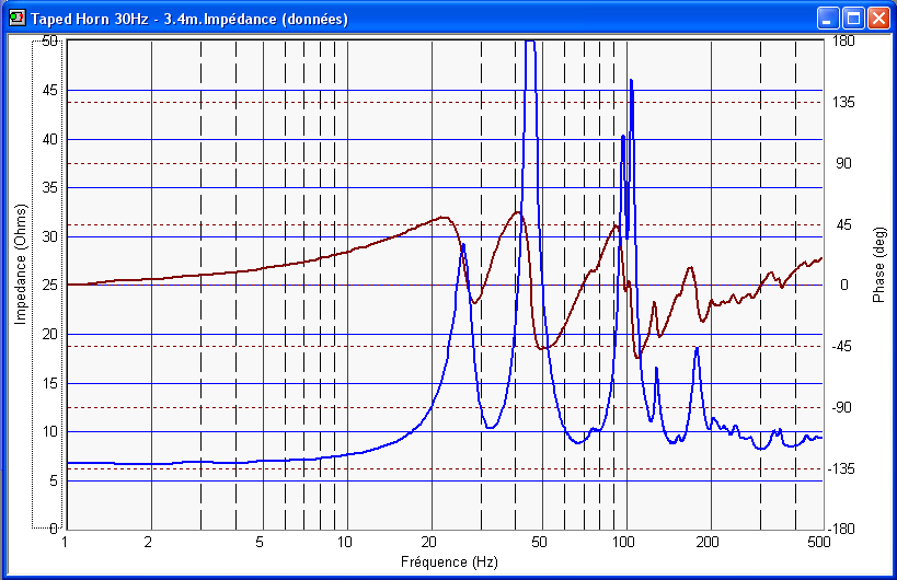
here are the impedance measurements...
Some answers (as much as I can)...
The top of the cabinet was screwed and I used foam joint (you know, for doors and windows) to improve sealing...
I do not really know if my measuring equipment is accurate. It is a Panasonic WM-61A mic and a "Eric Wallin" v2 preamp, but it never got calibrated. Can it be that off ?
I can borrow a digital SPL-Meter at the locakl Home Depot, would it be better ?
No response weighting either, how do you produce this ? Calibration ?
Yes, I am measuring indoors.
I think I will be Ok with the French version of Freqresplot 😉 😀.
I have measured with REW and SyncRTA as well, measure more or less match.... unfotnately. 🙁.
Thanks for your help.
@ jm_kzo
I ran a quick simulation with the values you posted - the frequencies of the impedance peaks you measured correlate well with the predicted peaks, though the magnitudes differ somewhat.
Any air leak from the high pressure side to the low pressure side or the outside - no matter how small - will alter the bass response.
Ask me how I learned this.....

Interesting that the lowest impedance peak is modeled as having the highest magnitude, yet has the lowest actual measured magnitude. Is there any damping in the cabinet? If not - this may indicate a leak. I'd check with the smoke from a candle or match with a 25 Hz sine wave playing (at the first impedance peak). Check your access cover and your external joints.
I'd suggest that you try an outdoor groundplane measurement with 2.83 V at 1M as others have suggested. Swept sine measurements work better for bass frequencies than impulse measurements do. Your mic capsule is the same as mine, though I am using a modified Radio Shack Analog SPL meter as a preamp. I'm pretty sure the capsule is not your problem, and if your preamp is built as Wallin designed it, I'm sure that it is flat too. I'm assuming that your soundcard is calibrated with a corrected flat response curve so that should not be an issue. The absolute SPL is of no concern here, as relative SPL is all you need to evaluate performance.
You might also consider moving the sub into a corner and checking the response in the room (which is the response that matters anyway).
For permanent construction, I use a polyurethane-based construction adhesive, as it expands and fills gaps very well. I use closed-cell foam weatherstripping as a seal for removable panels and lots of screws, but often have problems getting an effective seal with any removable panel.
jm_kzo said:
here are the impedance measurements...
I do not really know if my measuring equipment is accurate. It is a Panasonic WM-61A mic and a "Eric Wallin" v2 preamp, but it never got calibrated. Can it be that off ?
I can borrow a digital SPL-Meter at the locakl Home Depot, would it be better ?
No response weighting either, how do you produce this ? Calibration ?
Yes, I am measuring indoors.
I have measured with REW and SyncRTA as well, measure more or less match.... unfotnately. 🙁.
I can't think of anything ATM that can cause just the first peak in a TH to be well damped except an air leak. For sure it's not the < Sd driver cutout, though I agree that with rare exception it should be Sd (or larger if the driver can 'slap' the baffle at high excursion).
Never got around to trying the Wallin jig as too many folks had problems with getting them to work correctly, but your impedance measurement and close response match to the sim in its BW above driver Fs implies it's probably working well enough.
Typical SLMs OTOH roll off down low, so unless they have them periodically calibrated to be flat down to at least 20 Hz I would assume not enough to matter, but then your comments about lack of bass and high drive level required also implies an air leak, so if it were me, I wouldn't bother trying to chase down any other possibilities until I was sure that the TH was airtight.
On the cheap, you can get a RadioShack SLM and calibrate it per EW's tutorials.
SPL weighting should be selectable on the meter, so set it based on the type of signal.
Anyway, thanks for sharing and looking forward to an 'airtight' 😉 outdoor GP measurement.
GM
Re: Re: fb_TD10H
Not your basic rectangle, cool! Details?
GM
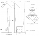
carpenter said:Just though I'd post a pic of my 18" tapped horn:
Not your basic rectangle, cool! Details?
GM
fb said:
Is that the peaks in the passband or above? I'll be using computer eq anyway, not sure if there'll be problems or not.
Doom doom doom.....Hehe. What effect will a ratio of 4.35:1 have? S2 of 115 makes freq response not happy again.
The two big ones just above the ~flat pass band. Not knowing how bad they will be in reality, I can only guess, but DSL's DTS-20 requires them, though if a parametric EQ is available you should be able to smooth them out enough for the XO to damp them down enough. That, or a very low, steep XO point/slope. Only one way to know for sure, but with such responses it seems like a good plan to be able to add any if necessary.
According to Tom Danley, a ~3:1 CR is pretty much the limit for prosound apps, but I've experimented with up to a 10:1 CR (same as Altec 1" exit drivers for a frame of reference) in various FLH loadings (including open back, i.e. BLH) without audibly damaging a cheap (assumed) 1 mm Xmax 'FR' driver at max peak HIFI levels (~115 dB/10 ft listening distance), though of course I did finally let its smoke out, ~bonding the VC to its gap trying to find its limits. Note that none of these proofs-of-concept designs were a 'sub' horn as I needed to keep size reasonable, but I see no reason why the results would be any different once scaled to the driver's specs, BW.
That said, none of the TH designs others have posted so far are reactance annulled AFAIK, or at least enough to allow a high CR at high excursion without the driver going non-linear as it did in all but one of my BLH configurations, so in these cases, dual (and especially quad), push-pull designs is your friend if just a single cab is used, though for HIFI/HT apps I personally wouldn't bother or worry about a high CR unless a small driver and/or one with specs that dictates an acoustically tiny cab requiring all its Xmax in normal (peak) operation is used.
GM
Re: Re: Re: fb_TD10H
Here's the dimensions:
GM said:
Not your basic rectangle, cool! Details?
GM
Here's the dimensions:
Attachments
reactance annulled AFAIK TH ?
GM: I'd like to add to my "GM says" notebook, the term you used in a TH post today, "reactance annulled AFAIK". Would you consider an explanation?
GM: I'd like to add to my "GM says" notebook, the term you used in a TH post today, "reactance annulled AFAIK". Would you consider an explanation?
I did an interesting test: I tapped on the cone of my 18" driver loaded in a bass reflex cabinet. The tone is deep, muted. I tapped on the cone of a copy of the 18" driver loaded in my tapped horn. The driver in the horn sounded like a drum skin on a large drum with twice the SPL.
This tapped horn business is one fabulous idea.
This tapped horn business is one fabulous idea.
http://www.diyaudio.com/wiki/index.php?page=Bass+Horn+FAQ
Not sure reactance annulling applies to TH? because by definition a TH doesn't have a closed rear chamber.
However, as a stupid thought... what happens if you put a small chamber with a long throw passive radiator in a TH, so that the center of the passive radiator is at S2... would that in effect allow some kind of reactance annulling? (and have the advantage of the large PR displacement feeding the horn?)
hmm... might have to try that one. Anyone know how to model that in akabak or hornresp?
I have a problem and I'm looking for informed opinions.
I've finally started to build my tapped horn (there are several very good reasons it took this long), all the pieces are cut and I've started glueing. A little fact that did not grab my attention on paper is just how narrow path is. (The plan was to line the entire pathlength in a fashion similar to littlemike's tapped horn.) My throat is only just over 1 inch wide, so the lining will have to be attached to the panels prior to installation.
I had planned on using fibreglass insulation and I already "separated" a 6 inch thick piece into ~1 inch layers. Getting it to separate into thinner layers isn't going to be possible, it just falls apart. These are still so thick they would fill up my whole throat area. So I started to look for something else.
I found some carpet underlay from an old model car. I'm pretty sure it's wool, it looks grey/pupleish and has strands of string running though it haphardly (not holding it together, just in the mix). This stuff is not strong, you can easily rip it apart with your fingers, I hope you know what kind of stuff I'm talking about. It's about 1 cm (1/2 inch) thick.
The problem with the car carpet underlay is that it is fairly dense, maybe so dense as to make my throat area seem smaller than it really is. My throat is only about 70 sq cm, 1 cm thick underlay will take up about 1/3 of the throat area, and that only accounts for lining one side.
So will "dense" lining make my csa (and throat size in particular) seem smaller?
what you are describing is bonded acoustic cotton, and yes the 6lb/cu.ft. stuff typically used in auto's is acoustically dense.
Best thought I have is 1/4" foam. (like mattress foam)
Best thought I have is 1/4" foam. (like mattress foam)
jbell said:http://www.diyaudio.com/wiki/index.php?page=Bass+Horn+FAQ
Not sure reactance annulling applies to TH? because by definition a TH doesn't have a closed rear chamber.
However, as a stupid thought... what happens if you put a small chamber with a long throw passive radiator in a TH, so that the center of the passive radiator is at S2... would that in effect allow some kind of reactance annulling? (and have the advantage of the large PR displacement feeding the horn?)
hmm... might have to try that one. Anyone know how to model that in akabak or hornresp?
Reactance annulling to get optimum LF response does apply the same as with a FLH, except you haven't got a variable size rear chamber to play with, only the compliance of the driver suspension.
So you need a driver with Fs considerably above the horn cutoff, the amount depends on the moving mass but is typically 50% higher than the horn cutoff for best results.
You can try this out by selecting "driver" in the tapped horn wizard and playing around with Cms.
Ian
klayman & Pruden patents
Rick57 posted a link to Klaman's 1962 patent, which turned out to be R.G>Pruden's US patent # 3047090, 31 JUL 62, filed on 7 May 58. The enclosure shows a horn with a variable CR member in the throat, as stated in citation #60: "Throat opening of said low frequency exponential horn from the chamber behind the louadspeaker may be varied so as to compensate for the different acoustical characteristics of different speakers, such as providing a hinged top member forming one side of the throat of the low frequency horn". One enclosure drawing is remarkably similar to the TH's being discussed here at DIY. There are several other tuning holes in another part of the enclosure.
Could the variable CR could be used as a tuning device on a "modern" TH?
Thanks jbell. How acoustically dense is it? Is it close to acoustically solid? For example, should I have made my pathlength larger by close to 100 percent the thickness of this lining material if it's what I intended to use? And rules of thumb here?
What's the acoustical density of fibreglass and foam? Should I be worried about them at all since I didn't account for them in the design?
What's the acoustical density of fibreglass and foam? Should I be worried about them at all since I didn't account for them in the design?
Re: reactance annulled AFAIK TH ?
As it pertains to a TH, pardon me for declining as I believe it's the key to getting the amount of acoustic power some DSL products measure Vs what folks sim/measure when they try to 'clone' some of them. Again though, I have no 'insider' knowledge of any of DSL's TH designs, so this is strictly a personal opinion based on what I've learned in my 'adventures' in horn design.
Regardless, until I can confirm for myself it's just a theory on my part, though Prof. Leach's math and Hornresp sims gives me high hopes. Also, I use the term 'reactance annulled' because it's the only way I can think of to describe the design routine, so it may not be the most technically correct, but unless someone can convince me that a TH can't be reactance annulled or at least close to it I'm going to continue to describe it as such.
Reactance annulling a FLH though is simply enclosing the rear of the driver with an acoustic compliance that offsets the horn's acoustic mass loading, i.e. if the driver has a free air resonance of 50 Hz and the horn lowers it to 25 Hz, then a high Q rear chamber is added to push the system resonance back up to 50 Hz.
GM
j.michael droke said:GM: I'd like to add to my "GM says" notebook, the term you used in a TH post today, "reactance annulled AFAIK". Would you consider an explanation?
As it pertains to a TH, pardon me for declining as I believe it's the key to getting the amount of acoustic power some DSL products measure Vs what folks sim/measure when they try to 'clone' some of them. Again though, I have no 'insider' knowledge of any of DSL's TH designs, so this is strictly a personal opinion based on what I've learned in my 'adventures' in horn design.
Regardless, until I can confirm for myself it's just a theory on my part, though Prof. Leach's math and Hornresp sims gives me high hopes. Also, I use the term 'reactance annulled' because it's the only way I can think of to describe the design routine, so it may not be the most technically correct, but unless someone can convince me that a TH can't be reactance annulled or at least close to it I'm going to continue to describe it as such.
Reactance annulling a FLH though is simply enclosing the rear of the driver with an acoustic compliance that offsets the horn's acoustic mass loading, i.e. if the driver has a free air resonance of 50 Hz and the horn lowers it to 25 Hz, then a high Q rear chamber is added to push the system resonance back up to 50 Hz.
GM
Post #3070
Hi just_a_guy,
Walmart, fabric stores and craft store handle Poly-Fil batting, see also:
http://www.batt-mart.com/site/490194/product/BM-BY-4466
It comes in all kinds of grades. The thin open pore foam will also work.
Regards,
Hi just_a_guy,
Walmart, fabric stores and craft store handle Poly-Fil batting, see also:
http://www.batt-mart.com/site/490194/product/BM-BY-4466
It comes in all kinds of grades. The thin open pore foam will also work.
Regards,
http://www.acousticalsurfaces.com/echo_eliminator/composite_panel.htm?d=0
I'm assuming you have something like this? Even at 1/2" it's about 1.0 from 500hz on up.
Air doesn't move through this stuff easily. It's recycled textile material (blue jean scraps, etc..) that's shredded, soaked with fire retardant, coated with polyester dust, and then heated to melt the poly and glue the fibers together loosly. As the fibers move, they translate movement into heat (due to the texture of the poly coated fibers)
I'd think that BAC would NOT be a good choice in a TH, as it'll be absorbing more than you want.
Foam, depending on density, on the otherhand is about transparent to bass, but will absorb HF, which is what I think you want. Tom seems to use poly batting, which would also be a candidate for 'transparent to bass, but decent HF absorber'
You can get thin poly batting or foam at your local craft / fabric store (like a joann's)
Post #3070
And sometimes glueing batting in place works well:
http://solutions.3m.com/wps/portal/3M/en_US/3M-Super-77/Super77/
Regards,
And sometimes glueing batting in place works well:
http://solutions.3m.com/wps/portal/3M/en_US/3M-Super-77/Super77/
Regards,
just a guy said:
What's the acoustical density of fibreglass and foam?
It's a design variable that the manufacturer specs. FWIW, I use the time honored 1" acoustic fiberglass insulation that historically could be found in bulk at big box building suppliers, so I assume there's Canadian equivalents: http://www.owenscorning.com/around/sound/commercial_acoustics/snd-attenuationbatts.asp
GM
I stapled 3/4" loft poly batting in place on three sides of the throat, then glued on the last side with another piece cut to fit stapled into place.
I had a split-throat design, so the actual area of each throat expanded from 90 to 180 cm^2.
If you're worried - use thinner batting than I did, I used the thickest I could find.
I had a split-throat design, so the actual area of each throat expanded from 90 to 180 cm^2.
If you're worried - use thinner batting than I did, I used the thickest I could find.
- Home
- Loudspeakers
- Subwoofers
- Collaborative Tapped horn project