Hi Russ,
Actually I'm planning to do the summation in the current domain since the dacs can be treated as well matched independent sources driving a transimpedance amplifier with 0 input impedance. There should be no interaction between the sources at all and the accuracy of current summation at each I/V converter should depend solely on the trim quality of the dacs.
Paralleling current source dacs by summing currents is a common practice - some even do it with resistor I/V conversion where you can expect some interaction between the dacs.
Should this not work well I plan to design a discrete based I/V converter to do the job.
kevinkr said:Hi Russ,
Paralleling current source dacs by summing currents is a common practice - some even do it with resistor I/V conversion where you can expect some interaction between the dacs.
Yes, I certainly agree that will work just fine. 🙂
Cheers!
Russ
Some of you may find this interesting:
http://www.diyaudio.com/forums/showthread.php?postid=1552427#post1552427
Cheers!
Russ
http://www.diyaudio.com/forums/showthread.php?postid=1552427#post1552427
Cheers!
Russ
COD revisited. 🙂
Well well well, Long time since I revisited this thread. But I have been playing around with COD again since I had some new things to test(JT2 code).
I have a couple of observations which some of you may find useful.
First... I think I have found a very very good setup for COD.
COD --> IVY basic (I will explain later) ---> JT2
Now here is the thing. The output of the COD is pretty darned clean. It does not really need heavy filtering as long as you use the fast rolloff digital filter. So, what I have done is setup IVY with just 392R feedback(I/V) resistors and no filter caps in feedback. None.
Now when I tested this (with my humble gear) the DNR and THD were pretty darn close to Buffalo. And it does sound very very good.
So any of you with a COD and IVY should consider ditching the feedback (filter) caps. I think you will discover a nice change of pace. 🙂
To me it sounds like an entirely new DAC.
Cheers!
Russ
Hi Russ,
please forgive my ignorance,
a) you are refering to caps C1-C4.
b) do we need to change the 357 Ohm resistors R1-R4 as well?
Cheers!,
Abraham Sidiropoulos
please forgive my ignorance,
a) you are refering to caps C1-C4.
b) do we need to change the 357 Ohm resistors R1-R4 as well?
Cheers!,
Abraham Sidiropoulos
Sidiropa said:Hi Russ,
please forgive my ignorance,
a) you are refering to caps C1-C4.
b) do we need to change the 357 Ohm resistors R1-R4 as well?
Cheers!,
Abraham Sidiropoulos
Hi Abraham,
No Apology required.
a) Yes, remove C1-C4.
b) 357R will work just as well as 392R, I just happened to have 392R at hand, so I used them.
Cheers!
Russ
Sidiropa said:Hi Russ,
should jumpers be placed instead of C1-4?
Best Regards,
Abraham
No, quite the opposite, just leave them open. 🙂
Cheers!
Russ

Anyone has listening impressions of the WM8741 chip?
As with their receivers, looks like wolfson dacs are snubbed by the diy audio community (not limited to this site).
As with their receivers, looks like wolfson dacs are snubbed by the diy audio community (not limited to this site).
JeroenR said:Can someone please take a look at my wiring schema? I'm not too certain I got it right....
Are the modules connected ok and is the grounding ok?
Thanks!!!
Jeroen
Anyone? Please?
Before I do the wrong thing with my iron today... 😀
Thanks,
Jeroen
Attachments
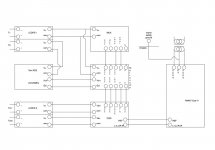
BrianDonegan said:I would join the two LCDPS GNDs at the supplies, then run a single ground to COD (they are both joined on the COD board). Also eliminate the I2S GND from Metronome.
Hi Brian,
Thank you for taking a look at it.
Why is joining the grounds at the PS better than joining at the boards? Is it preventing from current flowing between the boards? I sort of concluded that was not possible as the boards do not share a common. Is there current flowing through the I2S lines?
Thanks,
Jeroen
Just ground loop prevention. You would likely have no problems the way you had it. If you use the terminal blocks, you can pretty easily try it both ways.
BrianDonegan said:I would join the two LCDPS GNDs at the supplies, then run a single ground to COD (they are both joined on the COD board). Also eliminate the I2S GND from Metronome.
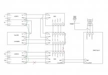
I soldered the boards, tomorrow I'll test with just some passive IV before I install the RAKK IV. Below is the adjusted schema, I did not add the clock to the common so it is isolated from the rest.
Jeroen
Attachments

I did not add the clock to the common so it is isolated from the rest.
I think you will want to link the grounds so the voltages will be relative.
BrianDonegan said:
I think you will want to link the grounds so the voltages will be relative.
The ground from the Tent clock-out is connected to the Metronome clock ground pad...
JeroenR said:
The ground from the Tent clock-out is connected to the Metronome clock ground pad...
That is fine, they will be linked there.
JeroenR said:
I soldered the boards, tomorrow I'll test with just some passive IV before I install the RAKK IV. Below is the adjusted schema, I did not add the clock to the common so it is isolated from the rest.
Jeroen
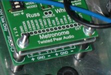
It works. 🙂
One weird thing though... The COD and Metronome are stacked. I thought it would be wise to add some shielding in between so I added a 1.5mm alu plate (see photo). This proved a bad idea: every time I touched the chassis the sound disappeared...

Anyone knows what happened? The alu shielding/plate and chassis were in contact through the screws but there was no ground/common from the circuit connected to the chassis???
Attachments
- Status
- Not open for further replies.
- Home
- More Vendors...
- Twisted Pear
- COD - Current Output DAC