With the help of the firmware you can choose the availability of i/o's (playback and records), using the mixer you can choose which of the available i/o's are active at the given moment.
Thanks, I think I've got enough confidence to continue with the schematics. This is a rather slow progress project, but I will report progress here.
Hello,
I have recently made a try to replace CM6631A with CM6632A as i found them to have the same pinout
Once i replaced it i got a message of uknown audio device so i put back the CM6631A
Has anyone tried the same before? Was the chip defective or it is just not compatible?
I have recently made a try to replace CM6631A with CM6632A as i found them to have the same pinout
Once i replaced it i got a message of uknown audio device so i put back the CM6631A
Has anyone tried the same before? Was the chip defective or it is just not compatible?
Hello,
I have recently made a try to replace CM6631A with CM6632A as i found them to have the same pinout
Once i replaced it i got a message of uknown audio device so i put back the CM6631A
Has anyone tried the same before? Was the chip defective or it is just not compatible?
They are compatible for pin-out but the software is different.
Before you remove the old chip, erase the f/w. Then flash new f/w for the CM6632A after you put it in. The f/w for the 6631A and 6632A are not compatible. You need 6632A f/w for the 6632A, putting 6631A f/w into a board with 6632A makes it hang during startup.
This is the original board with the 6631A
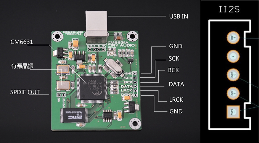
The 6631A is the one i want to replace with the 6632A so i can have DSD support
I have downloaded all tdtsai's documentation
What i want is only one I2S master output to connect the es9018k2m dac for stereo
I'll firstly read the ducuments and after that i'll return with more questions
Thanks
The 6631A is the one i want to replace with the 6632A so i can have DSD support
I have downloaded all tdtsai's documentation
What i want is only one I2S master output to connect the es9018k2m dac for stereo
I'll firstly read the ducuments and after that i'll return with more questions
Thanks
More pins needed
Hi,
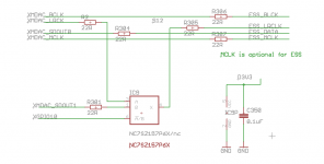
For DSD with ESS, you need 2 additional pins (data-1 and GPIO10) from the CM chip compared to PCM. Not sure if the board you're trying to use exposes these pins in an easy to connect way.
Schematic attached,
I have some (empty) 4 layer PCB's with the correct pin-out. PM me if you're interested.
Hi,
For DSD with ESS, you need 2 additional pins (data-1 and GPIO10) from the CM chip compared to PCM. Not sure if the board you're trying to use exposes these pins in an easy to connect way.
Schematic attached,
I have some (empty) 4 layer PCB's with the correct pin-out. PM me if you're interested.
Attachments
CM6631A schematics using S/PDIF input
Hi,
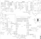
Now a first draft version of schematics around the CM6631A device using optical S/PDIF input, USB audio interface and I2S digital audio output to sample rate converter. Any comments are wellcome!

Hi,
Now a first draft version of schematics around the CM6631A device using optical S/PDIF input, USB audio interface and I2S digital audio output to sample rate converter. Any comments are wellcome!
Last edited:
Thanks for the comment!
As read from the CM6631A datasheet "RDMA#C supports S/PDIF input (192KHz is supported only with Crystal and PLL clock source)" My guess is that the firmware created by the Firmware Configuration Tool does not support this clock mode? Or is it an undocumented feature?
As read from the CM6631A datasheet "RDMA#C supports S/PDIF input (192KHz is supported only with Crystal and PLL clock source)" My guess is that the firmware created by the Firmware Configuration Tool does not support this clock mode? Or is it an undocumented feature?
My guess is that the firmware created by the Firmware Configuration Tool does not support this clock mode? Or is it an undocumented feature?
Don't know the answer myself. Maybe someone can chime in if they do. I was only commenting on the TOSLINK input but no SPDIF (coaxial), since TOSLINK is limited to 96kHz maximum sample rate with many devices due to problems with excessive jitter above that sample rate.
problems with excessive jitter above that sample rate.
Yes, jitter may be an issue at 192kHz. My "cure" to this is that I have a sample rate converter between the CM6631A and the DAC. Anyway, it seems like 192kHz might be hard to support from the S/PDIF input due to limitations in firmware.
No need for the reset IC, this was needed for 6631, but the 6631A has internal reset delay. Connect the reset button directly to the chip without capacitors. If the reset button has long wires, maybe add 10k pull-up. If the reset has (too much) external delay, it will cause the 'your USB device can perform better when connected to a USB 2.0 port' message. For better SPDIF performance, consider to use coax with pulse transformer instead of optical like suggested by others here. Pls note it looks like SPDIF-in to I2S out only works when the CM6631A is connected to a computer with USB and driver running. For the USB, you don't really need the ESD protection for home audio. Without the ESD part, the USB trace layout will be cleaner. It's USB 2.0 so must be matched impedance traces on PCB. Hopefully helpful.Hi, Now a first draft version of schematics around the CM6631A device using optical S/PDIF input, USB audio interface and I2S digital audio output to sample rate converter. Any comments are wellcome! View attachment 730169
Thanks for info regarding reset. Was not aware of the internal power up reset feature 🙂
The optical S/PDIF interface was selected by two reasons. Avoid risks for ground loop currents (but of course a pulse transformer solve this) and that the source in my case is optical. Jitter is minimized by a separate src to get the best possible working conditions for the dac. But due to limitations regarding 192kHz I'm considering to add an AKM4113 to get dual (opto + coax) and up to 192kHz. This device can be hw controlled and be connected to the CM6631A I2S input. A new version of the schematics next week.
The optical S/PDIF interface was selected by two reasons. Avoid risks for ground loop currents (but of course a pulse transformer solve this) and that the source in my case is optical. Jitter is minimized by a separate src to get the best possible working conditions for the dac. But due to limitations regarding 192kHz I'm considering to add an AKM4113 to get dual (opto + coax) and up to 192kHz. This device can be hw controlled and be connected to the CM6631A I2S input. A new version of the schematics next week.
Am I right in assuming that if you have an external micro controller then you can omit the parallel flash memory chip altogether and simply program the registers of the CM6631A/CM6632A yourself?
This then giving you all the overall functionality that coming up with your own firmware would, obviously minus the ability to utilise the on-board 5081 for using the I2C master etc?
This then giving you all the overall functionality that coming up with your own firmware would, obviously minus the ability to utilise the on-board 5081 for using the I2C master etc?
Hi,
Now a first draft version of schematics around the CM6631A device using optical S/PDIF input, USB audio interface and I2S digital audio output to sample rate converter. Any comments are wellcome!
View attachment 730169
Pin 10 VCC -> Digital power filter pin (2.5V), connecting external filter capacitors
Am I right in assuming that if you have an external micro controller then you can omit the parallel flash memory chip altogether and simply program the registers of the CM6631A/CM6632A yourself?
This then giving you all the overall functionality that coming up with your own firmware would, obviously minus the ability to utilise the on-board 5081 for using the I2C master etc?
What I am referring to specifically is in the information provided by tdtsai, in the OpenSource/Doc folder there is a file called 'register spec'. This appears to basically describe every single configurable/readable register on board the CM6631A/32A that can be accessed via the I2C slave module.
The chip itself appearing to have an address of 1000000, requiring you to first ping the chip at 01000000, followed by 01 (for USB register write access), then the relevant register you want to configure and then the values to write to the register.
Doing the above allowing you to configure the chip via a remote micro controller, rather than using the firmware/flash memory route. Has anyone actually tried this?
Hello everybody!
Does anybody have Axus Xonar U5 stock firmware by any chance?
It is CM6631A dac
Thanks
Does anybody have Axus Xonar U5 stock firmware by any chance?
It is CM6631A dac
Thanks
Has anyone yet determined a suitable replacement for the now obsolete pm39lv512 EEPROM chip that was commonly used with the CM6631A?
A new version of the schematics next week.
It took some more time to come up with a new version. The reason is that I had to add a CPLD mainly due to the need of a direct/drc switch and that the firmware of the CM6631A using the XMADC input interface uses 24bit left justified data and is master (my conclusion after reading documentation back and forth a few times). The design would have been more clear if it was a I2S slave interface. But as I dont want to go into firmware changes, I could not see another solution. Just hope it works.. Comment are more than wellcome 🙂
By the way, I'll keep the ESD diodes on the USB lines for extra protection. Impedance matching = yes I will do.
/Anders
Attachments
Both CM6631A and PM39LV512 difficult or impossible to get a hold of through official channels.
Are these parts at the end?
I really don't want to touch XMOS and the programming required.
Are these parts at the end?
I really don't want to touch XMOS and the programming required.
- Home
- Source & Line
- Digital Line Level
- CM6631 USB audio interface ... any good?