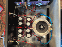
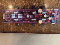
Tony, I, well, umm... yeah.indeed, I believe I can tell if they were plugged in or battery tools: Black and Decker batteries leave a memory distortion in the wood grain that exhibits a trace of glare for the french bassoons and violas.

The Aleph 60 monos I built this past summer are simply wonderful.
I always start with no assumptions. I would verify both loaded and unloaded PS voltages first.
Regards,
Dan
Regards,
Dan
Power supply voltage is 25.45 unloaded, a bit over 22 loaded. Using Randy's board with Antek AS4218 transformer.
Last edited:
I am by no means knowledgeable about this circuit. I’m just thinking through this if it were me. Isn’t it P2 that determines these voltages? So if all the voltages are approximately the same it indicates two things. One it was a good build because of the consistent voltages. And two, the consistent voltages point to a common cause. One of the the most frequent errors I’ve made in my DIY career is accidentally installing a component of the wrong value. When asking for help troubleshooting one of the greatest aids to those who would like to help is lots of pics. I’ve seen numerous time where a forum member has spotted a simple error in a pic.
Regards,
Dan
Regards,
Dan
Hi Randy,
I already removed one channel to double check everything. For the channel that is still in, here is what I have:
PS+: Unloaded - 25.42; Loaded - 22.02
PS-: Unloaded - 25.41; Loaded - 22.12
Right Channel:
CS 1: .747
CS 2: .749
CS 3: .738
OP 1: .751
OP 2: .770
OP 3: .741
Left channel had similar range prior to removing it.
I installed P1 and P3. I used a jumper for P2 and used a 820R resistor for R21.
Can you confirm the values of r19 and p3. Does bias value move when you change p3? What is min and max?
Confirm what values are in r16, 17, 18, and 20 as well.
Confirm what values are in r16, 17, 18, and 20 as well.
R19: 30K
R16: 390R
R17: 1K5 (measures 1K492)
R18: 1K5 (measures 1K492)
R20: 1K (measures .994)
P3: 50K
The bias moves when P3 is adjusted. Bottoms out just under 700mV. Goes up over 1V (stopped turning it up at that point).
R16: 390R
R17: 1K5 (measures 1K492)
R18: 1K5 (measures 1K492)
R20: 1K (measures .994)
P3: 50K
The bias moves when P3 is adjusted. Bottoms out just under 700mV. Goes up over 1V (stopped turning it up at that point).
Is your r14 from rail to far side of r14. In other words does it measure across both p1 and r14?
Correction (forgot to compare to new schematic)
R11: 4.89V
Z5: 8.89V
Q4 (R14 + P1): 3.6V
Q5: 4.73V
R11: 4.89V
Z5: 8.89V
Q4 (R14 + P1): 3.6V
Q5: 4.73V
Last edited:
I paralleled a 20K resistor with R19 dropping total resistance to 12K. I can now bias down to about 340mV. Bias holds steady but offset is a bit less steady.
I've attached snips from the ZTX450 and 2N4401 datasheets. Looking at the two transistors from the flat side with the pins pointing down, in both cases the pins going from left to right are emitter-base-collector. So no need to flip the 2N4401 around.


Edit: Datasheets referenced are from: https://www.onsemi.com/pdf/datasheet/2n4401-d.pdf and https://www.diodes.com/assets/Datasheets/ZTX450.pdf
Edit: Datasheets referenced are from: https://www.onsemi.com/pdf/datasheet/2n4401-d.pdf and https://www.diodes.com/assets/Datasheets/ZTX450.pdf
- Home
- Amplifiers
- Pass Labs
- Classic Aleph Amplifier for Modern UMS Chassis Builder's Thread


