Output filter perhaps?
I would guess the Behringer uses pre-filter NFB, so the amplitude and phase characteristics of the output low-pass filter directly affect the measured response. The switching frequency isn't likely to be the culprit, except that a higher switching frequency would allow the use of a higher cut-off frequency for the output filter, minimising the effect.
Class-D amps with post filter NFB, such as those from Hypex, greatly reduce the effect, although they can suffer adverse effects if the load is extremely reactive.
Yes, it's a pre-filter NFB design using the IRS20957s driver and the switching frequency is one MHz, checked it with oscilloscope..
What happens if I change the output inductor from 21 uH to, let's say 10 uH?
Joking [emoji87] [emoji86] ?the switching frequency is one MHz
It must be 320-350kHz.Not more.....
1MHz is a very high switching frequency for a class-D amplifier, normally it would be between 300kHz and 400kHz.
You cannot simply change the L or the C in the output filter on its own. The filter needs to be (roughly) matched to the load.
It might be useful for you to download the free version of TINA-spice from the Texas Instruments website and perform a few frequency response tests using a simple sinewave source. You could start with L=22uH, C= 1uF and R_load = 6 Ohms.
TINA is very easy to use and gives you a good insight into how component changes affect things.
the high noise content in the 10-20khz range could be the smeared difference freq of the two L/R modulators interfering . the idling freqs of the 2 channels should be either synced or at least 30khz apart.
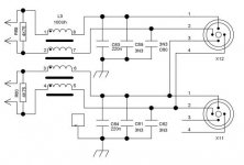
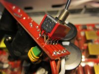
On the output board there's a ferro core with 4 separate windings. See picture and diagram. In my opinion, this will connect left and right channels with each other inductively. I'm familiar with Tina and P-spice, but I think this one will be difficult to analyze/simulate, involving two channels.
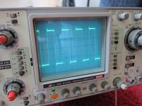
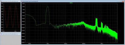
I shortened out the inductor with 4 jumpers(see picture), and measured again.
The noise is the exactly the same, but phase went from -180 deg to +180 in the same freq region. The sound now is improved, with more open/airy treble.(but not as good as my beloved Nad M3)
I shortened out the inductor with 4 jumpers(see picture), and measured again.
The noise is the exactly the same, but phase went from -180 deg to +180 in the same freq region. The sound now is improved, with more open/airy treble.(but not as good as my beloved Nad M3)
Attachments

You also have the noise peak at same frequencies with NAD M3, only less high ? Seems to have nothing to do with amplifier then ?
I guess the 100uH 220nF outputfilter does behave overdamped when load is below 32 ohm around 30kHz. Removing the outputfilter inductor: running a 400/800/3000 watt class D amplifier filterless could be considered.......... at least a bad idea.
I guess the 100uH 220nF outputfilter does behave overdamped when load is below 32 ohm around 30kHz. Removing the outputfilter inductor: running a 400/800/3000 watt class D amplifier filterless could be considered.......... at least a bad idea.
It' s not a filter for the working frequency , it's a common mode choke.The strait inductance for a two pole winding is not 100uH , it's not more than 1-3uH.[emoji121]I guess the 100uH 220nF outputfilter
https://en.m.wikipedia.org/wiki/Choke_(electronics)#Common-mode_chokes
Last edited:
OK so probably not entire outputfilter in that pic.
Ribbon (near flat and low impedance) frequency respons is only relevant if you want to use that ribbon as speaker.
Fixing noise that shows up in class A(B) ? NAD M3 output too, by modding the Behringer seems wrong to me.
Ribbon (near flat and low impedance) frequency respons is only relevant if you want to use that ribbon as speaker.
Fixing noise that shows up in class A(B) ? NAD M3 output too, by modding the Behringer seems wrong to me.
It' s not a filter for the working frequency , it's a common mode choke.The strait inductance for a two pole winding is not 100uH , it's not more than 1-3uH.[emoji121]
https://en.m.wikipedia.org/wiki/Choke_(electronics)#Common-mode_chokes
That's correct, there are only a few turns of each winding, cannot be 100uH.
I do not get consistent results, shall lend a another NU3000 from the music store.
There's definitely something wrong with my NU3000 phase wise.
It can , that small ring is ferrite with high permability , something about mu=6000-10000.cannot be 100uH.
The main inductor is wound on a T130-2 core , it's an ironpowder material with a permability of only 10 !!!!! And it has around 45turns making 22uH.
Отправлено с моего Lenovo P780 через Tapatalk
Hmm I saw this tread, so I am go asking something I get it not right, yes it is because class d is quite new for me and learning is always nice.
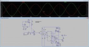
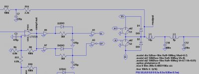
I have try these ones, however despite I have plus and minus 5 volts so ref is 0 volts the swing of the audio is only on negative side, This is what I want to ask why, because I see it is not as simple as it looks this D technology, I manage to get low HD, I do try get low HD without feedback and a full bridge.
It,s output voltage is not well, I did try a ucd feedbacked one who did work, so fellows, is there a teacher here for me😀 Normally we need to put the audio 180 degree for full bridge d amp, but is it also needed to flip the square output of the power mosfets? to prevent cancel them out..
In last pic you see single ended amp, strange it does only swing in negative part, while I have symmetrical supply everywhere.
regards
Attachments

Last edited:
I'm not sure what is going on there, yet a hunch is there might be duplication of more circuitry than should be done. I would use only one set of analog audio circuitry and then once the signal is level shifted down, use fast switching to produce the inverted and noninverted signals for both totem pole MOSFET drives. Something like CMOS logic chips to derive the inverted signals. I've done a circuit a bit how you are doing it, but with only one set of analog audio components, and it simulated well. It was a long time ago, so my memory is only general.
Something I just noticed is that your UcD version worked. It turns out that is all I have been using, even for years before I became aware of Bruno's patent, 100% post filter feedback, for as long as I can remember. It turned out that I was simulating almost identical circuit to the one in his patent artwork. I attribute it to lucky? chance and perseverance in my obsession for high power bass production almost twenty years ago.
Something I just noticed is that your UcD version worked. It turns out that is all I have been using, even for years before I became aware of Bruno's patent, 100% post filter feedback, for as long as I can remember. It turned out that I was simulating almost identical circuit to the one in his patent artwork. I attribute it to lucky? chance and perseverance in my obsession for high power bass production almost twenty years ago.
Last edited:
I'm not sure what is going on there, yet a hunch is there might be duplication of more circuitry than should be done. I would use only one set of analog audio circuitry and then once the signal is level shifted down, use fast switching to produce the inverted and noninverted signals for both totem pole MOSFET drives. Something like CMOS logic chips to derive the inverted signals. I've done a circuit a bit how you are doing it, but with only one set of analog audio components, and it simulated well. It was a long time ago, so my memory is only general.
Something I just noticed is that your UcD version worked. It turns out that is all I have been using, even for years before I became aware of Bruno's patent, 100% post filter feedback, for as long as I can remember. It turned out that I was simulating almost identical circuit to the one in his patent artwork. I attribute it to lucky? chance and perseverance in my obsession for high power bass production almost twenty years ago.
I am moved to a thread of mine own, there I do post in future, not all over diyaudio, it get's a mess.
Here I am, last post 116 very low distortion hysteric ucd, output 16 amps in 4 ohms.
http://www.diyaudio.com/forums/class-d/291403-amp-sound-12.html#post5294916
I have solved the problems here mentioned, just a learning proces.
regards
Last edited:
Ya, I noticed this problem simulating variations on the UCD circuit. Best idea I have is a buck converter for the lower bias that is also capacitor coupled to a diode above the +rail. Issue then becomes limiting that bias to follow the output, and cut it off when the output goes negative, and keep the diode that dumps the lower bias into the upper bias.Check the power supply for the high side switch. It may be dropping too low if it is normally refreshed by bootstrapping.
I have done this class d, it has very low distortions, but because it is a fase shifted one, in full bridge, I have the dead times done as in picture, I did see in simulation that the dead time through the mosfets do go cross each other on zero voltage, where afcouse is no shoot through, but di I have it right?, can someone explaine more from schematic, Maybe something is wrong but sim do well..
I have with post-prefeedback very low distortion on 20 amps 4 ohm output signal, the amp stays stable also with open output and full power, afcourse in simulation, not in real yet..
Thanks,
I have with post-prefeedback very low distortion on 20 amps 4 ohm output signal, the amp stays stable also with open output and full power, afcourse in simulation, not in real yet..
Thanks,
Attachments
- Home
- Amplifiers
- Class D
- Class D Design Issues