Maybe because the idea of a 2 KW half bridge is totally crazy, specially when i have the same amount of power with two half bridge configured in bridge, lower tension, lower stress for component, no bus-pumping, higher damping factor, higher sound quality cause higher switching frequency.
Maybe because the idea of a 2 KW half bridge is totally crazy, specially when i have the same amount of power with two half bridge configured in bridge, lower tension, lower stress for component, no bus-pumping, higher damping factor, higher sound quality cause higher switching frequency.
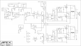
There is full bridge D4000
Assuming that a common class d amplifier have 90% efficiency, obviously a 2kw class D with Fsw of 40khz have much worse efficiency, a lot of car amplifier chinese board have this Fsw and have 70-80% efficiency, then we expect 400-600 watt of dissipation, in my opinion too much for two component
my d200 sounds very good i love the sound i will upload pictures after i put it in casing. and now im exited to build this sub amp
What does +15 LS mean? It's 15V referred to negative rail?
Yes, it's 15V referred to negative rail?
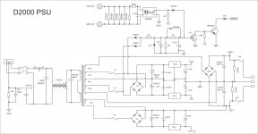
I will share PSU and Protect for this amps.
Hi Mile, nice to meet you.
What is the advantage using IGBT (slow switch) instead of mosfet with higher speed and comparable voltage level also. For now, my IGBT class D design is just idea. Some people rejected this idea as mosfet is going better and bigger.
Regards,
Kartino
What is the advantage using IGBT (slow switch) instead of mosfet with higher speed and comparable voltage level also. For now, my IGBT class D design is just idea. Some people rejected this idea as mosfet is going better and bigger.
Regards,
Kartino
Last edited:
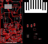
I need someone to check this, especially Mr Mile.
Suggestions welcome too
I will post sprint file...soon
Suggestions welcome too
I will post sprint file...soon
Attachments
Last edited:
Hello c08bm
greetings Thank you for taking the bull by the horns R1 R2 is 2 watt and same
should be on other igbt i am checking layout
warm regards
Andrew any email i can send you full schematic dont know why its not uploading
on forum
greetings Thank you for taking the bull by the horns R1 R2 is 2 watt and same
should be on other igbt i am checking layout
warm regards
Andrew any email i can send you full schematic dont know why its not uploading
on forum
So, a 4R7 5W could replace those 2 resistors, with "same should be on other igbt" you mean there should be 4r7-1nF on high side IGBT?
D
Deleted member 148505
Is IRS21844 more rugged and more tolerant to negative transient than IR2110? Circuit is very simple
So, a 4R7 5W could replace those 2 resistors, with "same should be on other igbt" you mean there should be 4r7-1nF on high side IGBT?
Nice work, use 4R7 2W instead 2x2R2/1W resistors.
LM311 and MC33078 must have decoupling caps 100nF from +15V and +15V to gnd (not on schematic).
Regards
Last edited:
Like this?
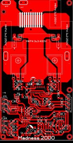
Sprint layout file attached
Nice work, all LM311 and MC33078 need separate 2 x 100nF decoupling from +/-15V rails to gnd.
You can made pcb for D2000 PSU, this PSU can be use for D4000 also.
Regards
Last edited:
Hello apexaudio
greetings is it possible for you to check pcb for mistakes i am also
checking for mistakes
warm regards
Andrew
greetings is it possible for you to check pcb for mistakes i am also
checking for mistakes
warm regards
Andrew
- Home
- Amplifiers
- Class D
- Class D Amp with LM566, LM393 and 2XIRF530