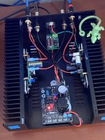
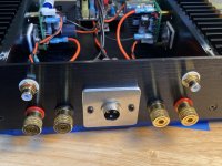
Another Lineup 4 Watter is born! This was an especially satisfying build because none of the parts, besides pcb’s, were bought specifically for this, even the chassis was repurposed.
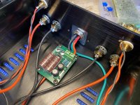
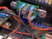
I robbed the Meanwell 24v, 5A power supply brick from my MoFo. Mark Johnsons nice little dc filter is inline before Jkuetemann’s capMx. Output is trimmed to 21.5vdc. The amp boards run a 1A bias current. This amp sounds pretty darn good for only 4 watts! My speakers in the main system are not an ideal match, being not very efficient.
Thank you Lineup for sharing your design. Prasi, your boards are always a pleasure to work with, thanks.
Joensd, your building tips were very helpful 😉. Time to let this newborn settle in…..Cheers!!
Attachments
-
 44B7F11D-EEF2-4490-AEFF-0EFA7C92968A.jpeg483.4 KB · Views: 567
 -
 66B1B59E-CAA1-44EC-B3F6-DFD98A1F8FA4.jpeg473.2 KB · Views: 544
 -
 F189A9A1-FE51-4D24-9CCE-05C72A963BE7.jpeg633 KB · Views: 545
 -
 56EAEB88-49A6-4081-9F62-62ADC0E35924.jpeg467.5 KB · Views: 556
 -
 2E81FCEA-2F97-4EC7-B75B-BD77FB21D2EF.jpeg595.4 KB · Views: 585

Another Lineup 4 Watter is born!
That's a very clean build.

May I ask what the thick pads are between the outputs and heatsinks?
jeff
Thanks!
I use these:
https://www.ebay.com/itm/TO-220-247...=p2349624.m2548.l6249&mkrid=711-127632-2357-0
I use these:
https://www.ebay.com/itm/TO-220-247...=p2349624.m2548.l6249&mkrid=711-127632-2357-0
What is the maximum recommended supply voltage, i have some spare Mean Well SP-150-24.
https://eu.mouser.com/datasheet/2/260/MWEC_S_A0007326910_1-2552099.pdf
It has adjustable output voltage from 22.8V to 26.4V.
https://eu.mouser.com/datasheet/2/260/MWEC_S_A0007326910_1-2552099.pdf
It has adjustable output voltage from 22.8V to 26.4V.
You can use higher voltages than 20V but unless you increase the bias, you won´t get any more output from the amp.
So it´s OK if your heatsinks can take the additional power dissipation.
If you´re fine with 4W (you can probably squeeze 5W+- out of the design as is), I´d adjust your PS down to 22.8V and use maybe a 2-stage RC-filter for further filtering. That would get you close to the original.
So it´s OK if your heatsinks can take the additional power dissipation.
If you´re fine with 4W (you can probably squeeze 5W+- out of the design as is), I´d adjust your PS down to 22.8V and use maybe a 2-stage RC-filter for further filtering. That would get you close to the original.
I like the topology, it could be the basis for a very nice headphone amp with say +15V and 100ma bias ?
Sure, especially, as X mentioned here, for difficult to drive/low impedance/low sensitivity headphones.
Otherwise (HP>=32Ohms) this beats it for simplicity:
formula 3hp
Otherwise (HP>=32Ohms) this beats it for simplicity:
formula 3hp
Nice build!!! great.. everything worked well including the cmx..Another Lineup 4 Watter is born! This was an especially satisfying build because none of the parts, besides pcb’s, were bought specifically for this, even the chassis was repurposed.
I robbed the Meanwell 24v, 5A power supply brick from my MoFo. Mark Johnsons nice little dc filter is inline before Jkuetemann’s capMx. Output is trimmed to 21.5vdc. The amp boards run a 1A bias current. This amp sounds pretty darn good for only 4 watts! My speakers in the main system are not an ideal match, being not very efficient.
Thank you Lineup for sharing your design. Prasi, your boards are always a pleasure to work with, thanks.
Joensd, your building tips were very helpful 😉. Time to let this newborn settle in…..Cheers!!
Thanks for the words... Always glad to...
Hi Vunce and prasi, well done on the build Vunce and you commentary. Can I ask if the Cap multiplier pcb by prasi was a GB or are the gerbers and relevant schematic available in a thread - if so, can you point me to it. I would like to get some of these made.
Regards,
Gary..
Regards,
Gary..
@Vunce , I seem to be following you around.
After my AKSA/Lender gets a proper case,
my M2x gets finished and housed,
my ACA Mini gets provisioned, started, finished, and housed,
I will be able to hear this to compare it to my MoFo (thanks again for the boards!)
In the interim, I'd be curious to hear how you think it compares.
Kind regards,
Drew
Can we use a TIP instead of the MJL transistors? Looking at the data sheet they are complimentary and most people used as getting genuine MJLs becoming difficult.
Thanks
Thanks
Looking at other builds I am going to use 2SC5200 pairs per channel.Can we use a TIP instead of the MJL transistors? Looking at the data sheet they are complimentary and most people used as getting genuine MJLs becoming difficult.
Thanks
Now coming to the higher wattage resistors per the schematic can I use 1ohm 2-3w metal film instead of the 1.2ohm? I do not have this odd value of 1.2R.
Thanks
Using Darlington transistors has been discussed before. Just go back a few pages.
1.2R? Can't see any in the s schematic. Want to parallel them instead of the 0R6?
Two parallel 1R=0R5 would increase the bias
1.2R? Can't see any in the s schematic. Want to parallel them instead of the 0R6?
Two parallel 1R=0R5 would increase the bias
I'm still curious about this idea.Typicallly 80mH and DCR of around 0R5. This is a BIG, heavy lump. But it can double efficiency to about 30% for a Class A.
Hugh
Would the inductor replace :
This feels like a MoFo?
Kind regards,
Drew
Post #105 of Prasi schematic the same boards I am using says use 2 of 1.2R resistors and hence I am using 1R as I have them in stock and sufficient heat sink so lets see if I can make it to run and not over heat with high bias. The board has parallel pair of 1.2R so I am good with 1R for now.Using Darlington transistors has been discussed before. Just go back a few pages.
1.2R? Can't see any in the s schematic. Want to parallel them instead of the 0R6?
Two parallel 1R=0R5 would increase the bias
https://www.diyaudio.com/community/...imple-circuit-great-sound.234515/post-6856822
With 20V supply and 0.6R you´d have ~1.05A current. With 0.5R ~1.25A.The board has parallel pair of 1.2R so I am good with 1R for now.
I would think so yes but I´d be not sure how how to easily control the bias without changing much otherwise.Would the inductor replace :
I have available some old original transistors A1980 / C5343, D2061 / B1369, in addition to the 2SC5200, do you think it is possible to do a test without major modifications? Could anyone try a simulation? Unfortunately I broke the old computer where LTSpice was running. Thank you
Dlis,

This is a simple CCS. BD139 is the sense transistor, and it always has 0.6V across base emitter.
With this voltage also impressed across R5, the current flowing will 0.6/0.6=1A (1000mA)
The current to drive the base of BD139 will only be very small, maybe 1mA or less, so that 999mA will flow into the 2SC5200 and it will be a constant because the Vbe of BD139 does not change.
The collector of the BD139 will settle at a voltage needed to ensure the 2SC5200 passes the necessary 999mA.
This is a CFP two transistor constant current source, well known, and delivering very good performance to very high frequencies.
HD
- Home
- Amplifiers
- Solid State
- Class A, 4 Watt, No Feedback, Simple Circuit, Great Sound