while waiting the parts to complete my aleph 30, I was impatient to get into the groove, so I ran across the citation 12 modified by nelson pass with complementary fets, schematic is really easy and quick to build, and I had all the spare parts here, so I made the first channel, and it immediately worked very well, no hum or noise, good bass but I can't juge as it's only mono, and my test speaker is quite small (bw solid 5 inch boomer!)4ohm
the only thisgs I changed from the original nelson modified schematic is that :*
for the complementary fets I used IRF 530/9530
the power supply is regulated (+/-32V) with 30Amps ballast darlington bipolars
my question to those who are familiar with this schematic, would concern the replacement of the end drivers with IRFP 240/9240
I already put them in place of the IRF 530/9530, and turned the bias resistor for a minimum bias, but should I put source resistors between the fets? (as in the actual schematic there aren't any kind of resistors...) whould they be necessary knowing that i intend to bias alittle high?
any input would be appreciated!
Vince
Source resistors on the MOSFETs are desirable in that they
help thermally stabilize the outpus and provide a resistance
where you can measure the bias. For this I suggest about
.47 ohms.
help thermally stabilize the outpus and provide a resistance
where you can measure the bias. For this I suggest about
.47 ohms.
Thanks Nelson,
I 'll try the 0.47 Ohms , and will try to run it in class A ,the second card is almost done, so I'll probably have stereo soon!
By the way just received the PASS DIY stickers they are great! again many thanks!
Vince
I 'll try the 0.47 Ohms , and will try to run it in class A ,the second card is almost done, so I'll probably have stereo soon!
By the way just received the PASS DIY stickers they are great! again many thanks!
Vince
I don't think you're going to get Class A off the Citation 12
heat sinks, or 60 watts Class A with a single pair of devices.
heat sinks, or 60 watts Class A with a single pair of devices.
actually I have big heatsinks here , and I just intend to push the 2 IRF240/9240 the just the highest I can , maybe 500mA each
would that be too much? this way I thought I'd expect the first watts to be class A , anyway this is my very first amp built from scratch, so I may be mistaking? would it make sens to try this kind of bias?
Vince
would that be too much? this way I thought I'd expect the first watts to be class A , anyway this is my very first amp built from scratch, so I may be mistaking? would it make sens to try this kind of bias?
Vince
I finally fired it up with the source resistors I could find (about 0.3Ohms)and a bias of about 100mA , worked great without any kind of problem of oscillation , and concerning the sound compared to the irf 530/9530 the 240/9240 are just terrific IMO, but I also made modifications to the PSU so maybe the improvment isn't due to the fets change only...
anyway this is a very simple circuit that just sound great, anyway I'll try a bit more bias , but I don't want to take much risk as it's well like that, so if anybody has advice concerning the improvement by setting a higher bias I'd be interested, I'm too scared to try it myself without advices before, as I heard so many times people getting their amps blown trying to search for perfection!
Vince
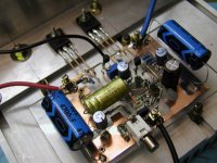
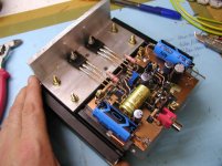
anyway great schematic Nelson minimalist and very efficient!!!
here is the pict of the amp under test:
anyway this is a very simple circuit that just sound great, anyway I'll try a bit more bias , but I don't want to take much risk as it's well like that, so if anybody has advice concerning the improvement by setting a higher bias I'd be interested, I'm too scared to try it myself without advices before, as I heard so many times people getting their amps blown trying to search for perfection!
Vince
anyway great schematic Nelson minimalist and very efficient!!!
here is the pict of the amp under test:
Attachments

Nice test rig - much cleaner than anything I do.
As to what you can get away with on 240's and 9240's, I
have run them as high as 50 watts dissipation with a 60 deg
heat sink temperature. Any more than that and I think you'll
be over the edge for reliability.
As to what you can get away with on 240's and 9240's, I
have run them as high as 50 watts dissipation with a 60 deg
heat sink temperature. Any more than that and I think you'll
be over the edge for reliability.
thanks for the info Nelson,
now I know how to stay around the safe area for them...
I am completing the second channel ...
much fun with this amp!
hope the Aleph 3 will also go smooth like that!
cheers!
Vince
😀
now I know how to stay around the safe area for them...
I am completing the second channel ...
much fun with this amp!
hope the Aleph 3 will also go smooth like that!
cheers!
Vince
😀
Hi Bob S
Sorry, for Q.
Do you have schemayic of Citation 12, I think it is very cheap amplifier & Ihope very good sound.
Sorry, for Q.
Do you have schemayic of Citation 12, I think it is very cheap amplifier & Ihope very good sound.
the amp schematic can be fount in the site passdiy.com
in the amplifier section under legacy project and it's name is citation 12, Nelson wrote a complete and very informative article describing the schematic...
vince
in the amplifier section under legacy project and it's name is citation 12, Nelson wrote a complete and very informative article describing the schematic...
vince
Well Now the 2 channels are working to give stereo listening, and I don't use no more my lab PSU regulated, but a non regulated one (21V transformer /35A bridge/ 2x47000mf caps
and here are the first impressions:
no hum or noise
and very clear and wide open stereo effect
very nervous and distortion free sound, in fact a really aenjoyable and involving stereo effect with no agressivity even played loud...
compared to the other amp I have here (onkyo 110W) the medium and highs are much smoother and in the same time seems more natural (not compressed)
But I have to admit that concerning the bass , they are not as good as the onkyo, less bass of course, but what lacks is definition I mean you don't feel the drums are between the speakers , sounds like it they were far away behind,
does anybody have an idea about what changes could be done to the schematic in order to modify the sound in the low end?
adding neg feedback? or upgrading the feedback current
change the gates resistors of 680 ohm for 220 ohm ones
or simply get more bias?(I setteled mine to 120ma)
any input would be apopreciated!
Vince
PCB Layout
I am intending to build the complementary MOSFET version using IRF 530/9532.
Before I do one, does anyone else have a PCB layout for this version please?
Also if I use +/- 40 volt rails what sort of power can I expect?
Thanks
Tony
I am intending to build the complementary MOSFET version using IRF 530/9532.
Before I do one, does anyone else have a PCB layout for this version please?
Also if I use +/- 40 volt rails what sort of power can I expect?
Thanks
Tony
There was a full set of good boards posted a couple of years or so ago by Ingvar Ahlberg (think his username was just that or maybe with an underscore.
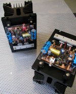
The 2 channels run now with 1A bias on each rail , nice sound eccept that I'd like to see what could be done to the schematic to get it tighter in bass...I have a third prototype that Iwill play with iconsidering that matter!
here are the twin amp blocks finished:😀
here are the twin amp blocks finished:😀
Attachments
Boards still available, both original and complementary version.
Layouts available too but but as they are double-sided designs
not that fun for home-etching. Actually i don´t think single sided , non plated through pcb´s are suitable for audio (although 96% or thereabout of comercial audioproducts are built on singlesided boards). Still it´s a very nice amp and well worth building. I run them at 1 amp/output device with 45-50V rails. Big heatsinks!
yes a top first amp to build , just tried it on JBL studio speakers 15 inch woofers, with only 29v rail and 1amp bias it's juts outstanding ,(actually much better on big speakers than on my tyny 4ohm lab bw)
- Status
- Not open for further replies.
- Home
- Amplifiers
- Pass Labs
- citation 12 mos fet