Hello
So that diode won't do much but won't do worse ?
Btw, did you do any update to that project since ?
Thank m. Pass
Gaetan
So that diode won't do much but won't do worse ?
Btw, did you do any update to that project since ?
Thank m. Pass
Gaetan
My dear DIY brothers:
I did citation 12 mos fet last week too,the sound quite good .each channel is handed with 2 IRFP240, but till now there are two
problems troubling me.
Firstly, when the voltage is large (eg: V=+-45V I=100mA), the IRFP240 is very easy destroyed.
Secondly, when the current is large (eg: V=+-35V I=1A), the IRFP240 is very easy destroyed too.
But it can work very good when the voltage is +-35V and the current is 100mA.
I had noticed the turn-on thump of C12, but is this the reason who destroyed the IRFP240?
Who can give me a favor about the explanation of this case.
Thank a lot!
Attachments
The voltage isn't too high for the devices, but perhaps your
bias is running high, and possibly you are seeing oscillation.
Can you monitor the bias currents?
😎
bias is running high, and possibly you are seeing oscillation.
Can you monitor the bias currents?
😎
FHigh Quality IRFP240 Push Pull Audio Power Amplifier Kit Based on Citation 12 | eBayriends,
I bought a plate amp citaion 12 on Ebay, the seller is not sure about it. I wonder if the transistor Q4 should be glued to the heatsink for thermal control? The scheme at the end of this page
Already many thanks for the information
I bought a plate amp citaion 12 on Ebay, the seller is not sure about it. I wonder if the transistor Q4 should be glued to the heatsink for thermal control? The scheme at the end of this page
Already many thanks for the information
I also made this amp before and still working right now...before q4 was on the board, it works but easily damage the mosfets ,so i pulled them up and screwed on the main heatsink and avoided the problem... this serves as thermal track transistor..
Very good Junm, grateful for the advice! It is a BC546B. I'll turn it heat to the heatsink and try your sound. What did you think of the sound? It is well detailed? Congratulations .....
.
.
Very good Junm, grateful for the advice! It is a BC546B. I'll turn it heat to the heatsink and try your sound. What did you think of the sound? It is well detailed? Congratulations .....
.
I used different transistors and power mosfets from hitachi...for me, sound is nice and has brilliant HF.
I made the connection heatsink, the circuit seems to be very stable. Did coupling audio with tantalum capacitors (10uf x 35v). The equipamantos MARANTZ NAD and have many of these capacitors in the signal line (audio), I confess, it was wonderful, if you want to try ....
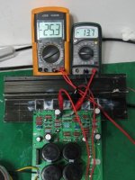
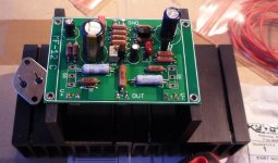
Would you mind posting a photo of the completed amp? I always worry buying a board of eBay, there may be mistakes in the board..
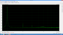
Those numbers are better than awesome! Great job. Thanks for sharing those pictures. A masterpiece and revival of a classic design.
I strongly advice Replacing R1 with a current source for the input diff pair.
Its obvious now when you look at the schematic that the input diff pair cannot control the VAS when the voltage across R1 is less then half the supply voltage, due the resistive load R2 (sized to split the current equally in the diff pair at normal operation)
Simply put when the supply voltage bellow about half the supply voltage Q3 is turned off and R3 and R4 acts as pull up on the Q6 putting what is left in the reservoir caps across the speakers...
Attachments
I strongly advice Replacing R1 with a current source for the input diff pair.
Its obvious now when you look at the schematic that the input diff pair cannot control the VAS when the voltage across R1 is less then half the supply voltage, due the resistive load R2 (sized to split the current equally in the diff pair at normal operation)
Simply put when the supply voltage bellow about half the supply voltage Q3 is turned off and R3 and R4 acts as pull up on the Q6 putting what is left in the reservoir caps across the speakers...
Wow, great catch!
Would like a pair too!
Arne K
Certainly! I have several boards just shoot me a PM, I can also include curve traced transistors for the input pair (2SA970).
- Status
- Not open for further replies.
- Home
- Amplifiers
- Pass Labs
- citation 12 mos fet


