What voltage do you have set on resistors R34 and R35 now? What voltage do you have for powering the input stage? What AC component for the power supply voltage - VAC? Is everything OK?
Trimmer P3 only sets the bias voltage on the output transistors. For testing and initial setup, do not connect more than one pair of output transistors. One pair is also enough for the first connection of a speaker or headphones (of course, through a resistor). If you should fire something - let it be only 2 transistors.
As BDP writes - your amplifier may oscillate. And it can help to increase the resistors to the gates of the input transistors from 100R to, for example, 470R or add capacitors C9, C10.
I built 3 such input stages with different transistors and I did not have to use larger resistors or capacitors C9, C10.
I think you have a mistake somewhere in the wiring.
@Fero_11
I set R34 R35 to ~50mV.
REG+ REG- both at some ~50.xxV, very stable. UNREG+ UNREG- also stable at ~37V.
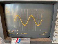
I just finished A/B test. Regardless of the tests I have done, the other channel should be intact, so I wired it up, first tested with an existing output stage pair, got same noisy waveform with abovementioned setting. DC output measured using DMM was ~1.7V.
Then I picked a new pair of MOSFETS, wired up and again with same setting. Same noisy wave form, DC ouput ~1.9V. The different thing being the wave form kept 'twitching', no deformation but jumping slightly on the screen.
Next thing I am going to try is try different resistor value for R34 R35. Might look at front stage wiring again too.
I did use a bit bigger UNREG capacitor, that shouldn't be the reason of this..?
I think bigger capacitor just stores more energy.
I set R34 R35 to ~50mV.
REG+ REG- both at some ~50.xxV, very stable. UNREG+ UNREG- also stable at ~37V.
I just finished A/B test. Regardless of the tests I have done, the other channel should be intact, so I wired it up, first tested with an existing output stage pair, got same noisy waveform with abovementioned setting. DC output measured using DMM was ~1.7V.
Then I picked a new pair of MOSFETS, wired up and again with same setting. Same noisy wave form, DC ouput ~1.9V. The different thing being the wave form kept 'twitching', no deformation but jumping slightly on the screen.
Next thing I am going to try is try different resistor value for R34 R35. Might look at front stage wiring again too.
I did use a bit bigger UNREG capacitor, that shouldn't be the reason of this..?
I think bigger capacitor just stores more energy.
Larger capacitors on UNTEG certainly don't matter. But for testing it doesn't matter. It doesn't really matter. It's enough that the voltage doesn't have a big ripple.
I don't think that replacing resistors R34, R35 will help.
Something is being overlooked. If both channels behave the same, the error is probably in the wiring. Not in the cable connections, but in the rewiring of the components. Unless something has gone bad, of course...
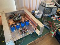
It's admirable that you started building the input section on a universal PCB. There's no shame in that. You've done it very nicely. Don't give up. I believe that you'll identify the error and solve it.
I don't think that replacing resistors R34, R35 will help.
Something is being overlooked. If both channels behave the same, the error is probably in the wiring. Not in the cable connections, but in the rewiring of the components. Unless something has gone bad, of course...
It's admirable that you started building the input section on a universal PCB. There's no shame in that. You've done it very nicely. Don't give up. I believe that you'll identify the error and solve it.

Typo, I mean changing gate resistor R32 R33. I have some extra 475Ω resistors.
But sure then look at wiring exhaustively again.
But sure then look at wiring exhaustively again.
OK I see it's 'gate resistors' rather than R32 R33.
I went thru my wiring of one channel, seems no error. So I started changing the MOSFET gate resistors to 220Ω. I bought a whole 100 piece box in the beginning for output stage so I still have some.
Also out of confusion I searched again 'how to measure opamp output offset voltage', and saw that auto excerpt: ground the input.
Reading these words I went back to the setup instruction page of β22 on AMB's site, that's where I first got to know output offset voltage. Now after all these years I read that sentence on the verge of the screen which I might have been skipping all along: if you don't have a volume pot connected, short the amp's input to signal ground.
Well I did read Fero's writing in this thread but I never really thought much about why shorting input to GND.
I also believe I did short to GND in earlier tries after reading it, but I don't quite recall any memory of solving output offset voltage problem. It's been haunting me til today so I definitely would remember if I solved such issue. Maybe I missed it somewhere.
Anyway double checking no live wires are hanging around, shorted input with GND, powered on, checked PSU voltage, re-tunedR7 R8 to ~1.010V.
Set R34 to ~56mV, output offset on DMM was 68mV.
Started tuning R7 R8 to search around, no problem going down to 0mV, it would drift between some -10mV~+18mV. I didn't wait for long to see how stable it can settle in, I still need to re-solder the gate resistors on the other channel so I can do all the fine-tune later.
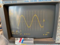
Sent in Sine wave signal 100mV, clean waveform popped up instantly. Yeah still slightly jagged but based on my previous tries this probably would be the cleanest I could get. Pulling off all those gate resistors again for higher value is definitely possible but I am not at all thrilled with this idea.
Going down to 30mV the wave would become noisier.
Still a few steps til a fully assembled ready for music A75, but I am a happy man. At least for now based on these test result. 😀
Will still post how it turns out later. Many thanks for the helping.
I went thru my wiring of one channel, seems no error. So I started changing the MOSFET gate resistors to 220Ω. I bought a whole 100 piece box in the beginning for output stage so I still have some.
Also out of confusion I searched again 'how to measure opamp output offset voltage', and saw that auto excerpt: ground the input.
Reading these words I went back to the setup instruction page of β22 on AMB's site, that's where I first got to know output offset voltage. Now after all these years I read that sentence on the verge of the screen which I might have been skipping all along: if you don't have a volume pot connected, short the amp's input to signal ground.
Well I did read Fero's writing in this thread but I never really thought much about why shorting input to GND.
I also believe I did short to GND in earlier tries after reading it, but I don't quite recall any memory of solving output offset voltage problem. It's been haunting me til today so I definitely would remember if I solved such issue. Maybe I missed it somewhere.
Anyway double checking no live wires are hanging around, shorted input with GND, powered on, checked PSU voltage, re-tunedR7 R8 to ~1.010V.
Set R34 to ~56mV, output offset on DMM was 68mV.
Started tuning R7 R8 to search around, no problem going down to 0mV, it would drift between some -10mV~+18mV. I didn't wait for long to see how stable it can settle in, I still need to re-solder the gate resistors on the other channel so I can do all the fine-tune later.
Sent in Sine wave signal 100mV, clean waveform popped up instantly. Yeah still slightly jagged but based on my previous tries this probably would be the cleanest I could get. Pulling off all those gate resistors again for higher value is definitely possible but I am not at all thrilled with this idea.
Going down to 30mV the wave would become noisier.
Still a few steps til a fully assembled ready for music A75, but I am a happy man. At least for now based on these test result. 😀
Will still post how it turns out later. Many thanks for the helping.
Attachments
Congratulations on your progress in the project.
As I have recommended a few times, it is a good idea to read the instructions for building this amplifier very carefully.
The shorted input or potentiometer must be completely pulled to GND during the entire period of adjusting the bias voltage and output offset.
The transistor (Q11 - original scheme, Q9 - my scheme) is best placed on a heat sink near the output transistors. They will heat up the same way and the bias voltage stabilization will be better.
Setting all voltages must be repeated after the amplifier warms up. But all this is also nicely described in the original documentation. The input transistors must be paired - again it is written in the documentation.
And again check, check, check. Connecting components according to the scheme - extremely important. Connecting cables - extremely important and also high-quality power supply.
When you think everything is in order, you can increase the bias voltage on resistors R34, R35 with trimmer P3. It depends on what power you want in the A-Class, how many pairs of output transistors you will have connected, what heatsink you will have and what power transformer you will power it with. Then try setting it to about 150 - 200 mA and see. Again, you need to read the documentation.
These are all small steps that lead the project to successful implementation.
Just keep going - all these solutions to the problem are pushing you further.