@Zen Mod
What I haven't understood are why C5 C6 actually only get 5V, and why zener voltage equals voltage across zener diode. I thought zener voltage is just threshold, not the voltage actually goes through.
Above are I will study next.
For why 16V capacitors are enough, yeah I totally get this part.
What I haven't understood are why C5 C6 actually only get 5V, and why zener voltage equals voltage across zener diode. I thought zener voltage is just threshold, not the voltage actually goes through.
Above are I will study next.
For why 16V capacitors are enough, yeah I totally get this part.
C5 and C6 are tied to the MOSFET's (Q3,Q6) turn on voltage. Remember the "gate-to-source" thing I talked about in post #2?
Voltage does not "go through" a component. Voltage is a difference of potential between two points. The 9.1V zeners are used for voltage reference. If I remember correctly the current "through" the zener (Z1,Z2) was chosen to be about 4mA. This keeps the dissipation of the zener, and the series resistor (R11,R12) at a safe and sane level. C3 and C4 are just filtering out some zener noise, for a more quiet "reference". A desirable trait..
Voltage does not "go through" a component. Voltage is a difference of potential between two points. The 9.1V zeners are used for voltage reference. If I remember correctly the current "through" the zener (Z1,Z2) was chosen to be about 4mA. This keeps the dissipation of the zener, and the series resistor (R11,R12) at a safe and sane level. C3 and C4 are just filtering out some zener noise, for a more quiet "reference". A desirable trait..
Last edited:

Still working on assembling slowly.
Got a few questions wonder if anyone can help.
Q1.
I realized I need some minimal parts adjustment for the amp to be working at 4Ω load.
The MJE15030/031 are rated 8A continuous, but since they are driving the front end not the output stage, I need not change them?
Q2.
In the design the output stage is driven by unregulated power supply, is there a reason for using unregulated power?
I do have a faint memory reading somewhere that unregulated power doesn't make a difference to this kind out MOSFET application.
Hi,
Depending of the number of mosfet at the output you could reach less than 2Ω quite easily, my A75 with 2*12 mosfet by channel is not stalling on low impedance speakers...
Answer for Q2: you are working in Class A so the current in the power supply is quite constant, so no need of a regulation!
Depending of the number of mosfet at the output you could reach less than 2Ω quite easily, my A75 with 2*12 mosfet by channel is not stalling on low impedance speakers...
Answer for Q2: you are working in Class A so the current in the power supply is quite constant, so no need of a regulation!
@Alain Dupont
I thought the load is at the speaker and the amp reacts to the load, rather than due to the amount of mosfets?
I do know the resistance rating of speakers are nominal.
I thought the load is at the speaker and the amp reacts to the load, rather than due to the amount of mosfets?
I do know the resistance rating of speakers are nominal.
@Alain Dupont
Ok I think I got it.
I realized yesterday that Class A 'always consumes that much energy, it's a matter of efficiency'.
At idle all is dissipated as heat, as music starts going some is converted to sound wave, therefore 'efficiency'.
Just that that ceiling of efficiency is very low.
What I did not realize was that it means current out of power supply is constant. I used to thought the phrase 'X watts into Y Ω' means 'fluctuating within X watts'.
Thanks, now I can look further into this principle of Class A.
Hi guys, got a fundamental question about load, power output and current, hope someone can help.
A75 was designed to be able to run 75W at 8Ω load, and based on this the idle current, peak current, power dissipation were calculated, in order to choose appropriate transformer and design heat sink.
My question is, does that current means per positive output/negative output? which means, for example, for 8Ω, peak current 4.3A means 8.6A in total for 1 channel, which doesn't make sense as the default fuse was 6A at AC filter.
I mean I know there are voltage rules and current rules for circuit but I am not really sure how it works here.
Or does it have to do with the magical current bias of push-pull Class A amp, so current is doubled? I happened to just read that in The Pass Zen Amplifier earlier today.
Attachments
@Zen Mod
So is it the simple rule of Power = Voltage times Current?
Across transformer voltage was ~3 times higher so with same power output, current is much lower.
I also read now that
4.3A peak current at +/- ends are after amplification. I think.
I went into this rabbit hole because I was checking whether anything I should pay attention to aside from transformer and heat sinks, if I would also use it with 4Ω.
So is it the simple rule of Power = Voltage times Current?
Across transformer voltage was ~3 times higher so with same power output, current is much lower.
I also read now that
And thinking back, for A75, output devices operate at about 200mA each, so input current to output stage is at most 2.4A.Push-pull amplifiers generally operate in Class A mode up to a point where the output
current is twice the value of the bias current.
4.3A peak current at +/- ends are after amplification. I think.
I went into this rabbit hole because I was checking whether anything I should pay attention to aside from transformer and heat sinks, if I would also use it with 4Ω.
If you have the opportunity, I recommend using the Harris P channel mosfets instead of the IR. They give lower distortion at the upper mid and high end.
@Zen Mod
I know how the components works, but thanks for the links.
I never thought about checking out the actual First Watt site.
@Nelson Pass
Yeah I did read about the performance at mid- high range between IR and others from one of the old threads about A75 here.
Thanks for suggestion.
I know how the components works, but thanks for the links.
I never thought about checking out the actual First Watt site.
@Nelson Pass
Yeah I did read about the performance at mid- high range between IR and others from one of the old threads about A75 here.
Thanks for suggestion.
I know how the components works, but thanks for the links.
maybe my bad, Pa didn't wrote much about Class AB amps in that article
but, it's simple as this - if your amp is AB class, declared/having 75W/ch, take at least 200VA xformer for that channel
that's pretty much in line (taken up from "at least") with quote from article, mid of page 1, part 2
The transformer is a 500W toroid with dual 115V primary and 30V AC secondary coils. Figures 11 and fig. 16 show the hookup of the primary coils for both 115V and 230V operation.
https://www.firstwatt.com/pdf/art_a75_1.pdf
https://www.firstwatt.com/pdf/art_a75_2.pdf
Oh yeah the transformer rating part got me surprised, that one channel of 200W rating Class A need to have a 3000W transformer.
Back when I started working on this, I read through the article and bought two 500VA transformers.
Assuming 150W (avg) into 4Ω scenario, one channel is around 324W as in the article.
Back when I started working on this, I read through the article and bought two 500VA transformers.
Assuming 150W (avg) into 4Ω scenario, one channel is around 324W as in the article.
Hi @seann
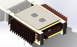
Nice to see a build of a A75.
Not sure where you are at your build right now, but once you have a look at the construction of the front end, I can recommend having a common heat sink for all the front end mosfets. This will make the amplifier much much easier to trim, due to temperature change, heat up etc.
Regards Mikkel
BTW does anyone have the original Gerber files for the PCB’s🙂
I am considering to rebuild my front end due some repairs and slight differences in the two channels. I also have a friend who has a damage PSU board…
Thanks in advance and any help is appreciated ☺️
Regards Mikkel
I am considering to rebuild my front end due some repairs and slight differences in the two channels. I also have a friend who has a damage PSU board…
Thanks in advance and any help is appreciated ☺️
Regards Mikkel
I found this a while ago, looks like they are still selling the front-end pcb:
https://www.hifiocean.biz/collectio...lass-a-mosfet-power-amplifier-front-end-board
Otherwise, i have EAGLE-files of my old pcb-design, it combines psu+front-end for one channel.

https://www.hifiocean.biz/collectio...lass-a-mosfet-power-amplifier-front-end-board
Otherwise, i have EAGLE-files of my old pcb-design, it combines psu+front-end for one channel.
- Home
- Amplifiers
- Pass Labs
- circuit questions for Pass Thagard A75