I'm comparing the Eico HF-87 clone to my Williamson UL mono's and it is a close one... They both sound great, but I think the HF-87 clone just might have the egde. I hate to say it.
The simplicity of the HF-87 is alluring and it sounds quite amazing.
Oh, I think the Eico HF-87 is a wonderful amp. Many years ago I bought one at a local stereo shop. They didn't think it was anything special and priced it at $200. I asked them to hook it up, which they did, to a pair of small Vandersteens. The owner happened to wander by the demo room, listened for a moment, and said, "Boy did we underprice that!" The subsitution of the 12AX7 for a more typical pentode in that type of circuit it very sweet to listen to, IMO. I used it for a long time but traded it away for something else eventually. I still have a pair of the output transformers, I should build a copy myself.
Last edited:
LOL so I just getting to this build now!!! I now have 2 800vct power transformers. The electrohome schematic calls for a 5v4g so I guess I'll go with that
Even though the tube sheet says normal is 10uf and 4uf is better. I'm putting these amps in pretty small chassis but I think they will work ok. I harvested two old electrohome 72 6v6 PP radios that i took the iron out of and built 2 supro amps using 5cz5 power tubes. Anyway With some thought these chassis should work fine. I', taking grover's advice and omitting the second choke.
Even though the tube sheet says normal is 10uf and 4uf is better. I'm putting these amps in pretty small chassis but I think they will work ok. I harvested two old electrohome 72 6v6 PP radios that i took the iron out of and built 2 supro amps using 5cz5 power tubes. Anyway With some thought these chassis should work fine. I', taking grover's advice and omitting the second choke.
Attachments
Last edited:


I have a good stash of 6P3S-E i've had for years. I'm hoping to try these in this amp. The 4 Valve Art KT-66 I have I purchased
in 2005 but have been used in several guitar amps over the years.
in 2005 but have been used in several guitar amps over the years.
Yup, keep them out of sight. 😉I'll hide that underneath!
Same. Great sounding tube.I have a good stash of 6P3S-E i've had for years.
jeff
Great tube indeed, I use them on a HF-89 inspired amp, work really well.I have a good stash of 6P3S-E
Making the best of these days before the snow flies!
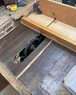
Started the day watching youtube, on how to make a box finger joint jig.
Too many were too involved. I ended up just making a quick and dirty little sled, attached to my miter gauge from some scrap pieces.Note the missing saw insert LOL! Worked ok, but I'll need to take the belt sander to the sides to smooth the joinery. Trim is white oak cut back in 2001 on my fathers property.
I used clear construction adhesive but will put some screws through the chassis into the wood later. Put them in front of the wood stove to help dry the glue.
Attachments
Hi THD+N! No I'm super busy as of late. Thanks for your interest though. I plan to use eyelets and boards.
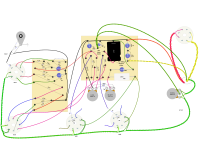
Here is the rough layout if you are interested. I like eyelets, because is so easy to change values. Hope to get going soon,
but Christmas tends to be busy too!
Cheers!
Here is the rough layout if you are interested. I like eyelets, because is so easy to change values. Hope to get going soon,
but Christmas tends to be busy too!
Cheers!
Attachments
Nice mild day on the Canadian prairies today. Fired up the wood stove this morning in the workshop and got a bit done today.
Still have some mechanical stuff to do and may router out the back, down shy of the steel and do the access that way, or a series of holes
with the hole saw for the ac, speakers, fuse input etc.. I have a 5" x 12" x 1inch thick piece of Jatoba wood that I thought I use to
make medium size volume knob on the front of each. Hopefully I can get back to these soon!
Attachments
![IMG_4827[1].png](/community/data/attachments/1302/1302241-21870abac3a0bab537636097ca6b119c.jpg?hash=7HXOy9-8gN)
![IMG_4828[1].png](/community/data/attachments/1302/1302242-ae829c1022c77fb1d5da37e153974c50.jpg?hash=DN7POVEHf1)
![IMG_4830[1].png](/community/data/attachments/1302/1302243-42e154b3d36d2cfde13bc97361409510.jpg?hash=GS0NhOl_yB)


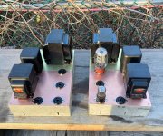
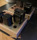
I just finished up three Williamson inspired UL amps (only a pair are shown) I am making a total of 7 for a home theater set-up.
I am using 1625's and 14N7's for tubes.

I am using 1625's and 14N7's for tubes.
I know you have received a lot of advice and recommendations throughout this post, but I would offer one more suggestion... stagger the low frequency time constants further apart than the ones used in the PA-600 schematic.
0.22uF/470k = 1.54Hz
0.22uF/100k = 7.24Hz, this represents a ratio of 4.7 which is not very wide and will lead to documented low frequency instability in the a Williamson type amp.
A simple and very effective modification to the original circuit will yield excellent low frequency performance with no instability issues. Use the following cap values instead:
2.2uF (400V (min)/470k = 0.15Hz
0.1uF (400V)/100k = 15.92, this gives you a ratio of 106 which will make the first stage (2.2uF/470k) essentially direct coupled. This info is from threads on AudioKarma. I've used it in many amps and it works wonders.
For the input into the 1625 grids, I am actually using 0.047Uf/400V Orange Drops/220k. Works great, no issues.
- Home
- Amplifiers
- Tubes / Valves
- Circuit ideas for KT66 stereo amp