Hi Kashmire. Think of the output stage as being like a linear voltage regulator with two loads in parallel - the choke and the speaker. In your cct they are in parallel AC-wise provided you have a perfect power supply. When there is some ripple on the supply the choke will be fed quiet DC but the other end of the speaker will get fed hum, so it will hum. I like the idea of puting the speaker across the choke. Then, if you still need a coupling capacitor it need only be a very low voltage one, but truly gigantic capacitance if you want. 😉
My preference is to have everything "earthed" at the one rail - input connector, tube cathode cct, bias zener, choke, and speaker.
Edit: The speaker will get fed hum if it is "earthed" to the opposite rail to that which the bias zener is "earthed", whether earth be positive or negative.
My preference is to have everything "earthed" at the one rail - input connector, tube cathode cct, bias zener, choke, and speaker.
Edit: The speaker will get fed hum if it is "earthed" to the opposite rail to that which the bias zener is "earthed", whether earth be positive or negative.
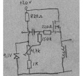
Fuling: the bias circuit you posted is much closer to how this circuit would be actually implemented. I’ve changed the simulation to a more realistic circuit below.
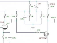
Circle: you are correct about the noise problem – except you didn’t take the input stage into consideration. The output stage by itself conducts power supply noise to the load with unity gain (1 volt power supply noise results in 1 volt loudspeaker noise). However, when connected to the input stage, the conducted noise drops down by a factor of 10 or more (actually, more like 50). I’d probably be happy with this performance. Since the tube input stage is inverting, power supply noise could be intentionally injected into the signal, applying anti-noise into the system.
If that doesn’t make you comfortable enough, I’ve added in a 220uF capacitor in the gate bias circuit, which drops noise down even more. This capacitor is technically not in the signal path – it is separated by the 100k resistor – but it does affect noise performance.
Why am I going through this much trouble? Because if the load is connected across the choke, any output at the load will cause an equal ripple on the power supply. To deliver +/-2A at the load, the power supply would see 2A continuous with a +/-2A ripple (4A peak). With such large ripple currents, massive power supply capacitors would be required. In addition, that means the power supply capacitors are part of the signal path (the AC current through the loudspeaker must also flow through the power supply capacitors). By placing the load across the active device (MOSFET), the power supply current is continuous 2A, thereby allowing usage of power supply techniques that are happy with steady-state current loads (such as active capacitor multipliers).
Attachments
Hrm... It seems people spend a lot of time trying to get extremely clean regulated power supplies. Last semester we spent the whole time learning about frequency responses of LTIC and other LRC circuits, but I'm not sure how to apply those techniques to something which has a variable load and such. Does anyone know of any good books I could check out of the library to learn more about these sorts of circuits? I'm just a poor student, so I can't actually build many different designs, but I'd still like to learn a thing or two. I basically understand the basic underpinnings of the various schematics I've seen around but it would be nice to get a more solid understanding.
Cheers,
--Peter
(can't wait till my aleph-x boards to come, that will be some fun stuff.)
Cheers,
--Peter
(can't wait till my aleph-x boards to come, that will be some fun stuff.)
The 1 Ohm resistor represents the DCR of the choke. I used 1 Ohm for simulation purposes. The real choke may have a different DCR (hopefully lower).
This week I´ve had some luck sourcing parts for my balanced amp project: Four beercan sized caps (110 000µF) and six smaller (15 000µF) plus a pair of BIG heatsinks.
Together with some caps I already had the total capacitance will be 688 000µF, so I have good hope of a smooth rail voltage😀
Now I only need to find a pair of cheap 12V >200VA transformers.
Together with some caps I already had the total capacitance will be 688 000µF, so I have good hope of a smooth rail voltage😀
Now I only need to find a pair of cheap 12V >200VA transformers.
djk said:
80mH is good for a 3dB down point of 16hz with an 8 ohm load, doesn't matter whether it is 5W or 500W.
How did you calculate this??
Cheers
Magura
The inductive reactance of a choke is calculated as
XL= 2*pi*f*L
The basic rule is to keep the reactance higher than the load impedance at the lowest frequency that is to be reproduced, and the reactance of a 80mH choke at 16Hz is 8 ohms.
XL= 2*pi*f*L
The basic rule is to keep the reactance higher than the load impedance at the lowest frequency that is to be reproduced, and the reactance of a 80mH choke at 16Hz is 8 ohms.
Fuling said:The inductive reactance of a choke is calculated as
XL= 2*pi*f*L
XL =?
f=?
L= inductance??
Cheers
Magura
XL= Inductive reactance (in ohms)
f= Frequency (in Hertz)
L= Inductance in Henrys
Try it: 2*3,14*16*0,08 = 8
f= Frequency (in Hertz)
L= Inductance in Henrys
Try it: 2*3,14*16*0,08 = 8
Whats better?
Ok,
What is better.... Push Pull MOSFET Source followers with a split choke load on outputs with a step-up input tranny? Or not configured as source followers with a 1:1 input tranny and a 64:8 output transformer???
Thinking about building either one.
Thoughts?
Ok,
What is better.... Push Pull MOSFET Source followers with a split choke load on outputs with a step-up input tranny? Or not configured as source followers with a 1:1 input tranny and a 64:8 output transformer???
Thinking about building either one.
Thoughts?
I´d say source followers with tube input stage, since I have some doubts about stepup input transformers.
But an output transformer would be kinda cool, though...
But an output transformer would be kinda cool, though...
If it were just a single stage
If we forget the tube input stage....
would a source follower with CT chokes as loads and a 1:10 step-up trying to drive the gate capacitance be better than one with a 64:8 output tranny and a 1:1 input transformer?
either way the gate capacitance is a problem.. amplified by the 1:10 step-up or very large due to the MOSFET having gain?
Is it better to have gain in the MOSFET or transformers???
but i guess using a OPT and a 1:1 input... using say the BUZ900 series... only has to swing 1v or so on the input.
Thanks for your reply.
Oh, single stage!
In such case I´d say gain in the mosfets.
I guess you have seen:
http://www.diyaudio.com/forums/showthread.php?threadid=18103&highlight=
In such case I´d say gain in the mosfets.
I guess you have seen:
http://www.diyaudio.com/forums/showthread.php?threadid=18103&highlight=
input capacitance
question is input capacitance....
if i configure the MOSFET as a voltage gain device and use an OPT.. then would the input capacitance be too much??
Which would be less of a load on the pre-amp?? high cap due to the possible 1:10 input tranny or high cap due to the gain of the MOSFET??
Or am I barking up the wrong tree and should be concentrating on the output side?
I don´t know how much capacitance that is too much, but I guess a decent preamp is needed for both.
I think high capacitance/low impedance inputs is the curse of single stage amps, and I don´t have any clever ideas of how to get past it.
Maybe a JFET input buffer or something, but it would no longer be a true single stage amp.
I think high capacitance/low impedance inputs is the curse of single stage amps, and I don´t have any clever ideas of how to get past it.
Maybe a JFET input buffer or something, but it would no longer be a true single stage amp.
I'm building a Frankenstein, it is:
input selector switch
volume control
voltage gain stage (6C45Pi running open loop)
three-way filter (crossover)
class A FET follower w/choke for tweeter
class A FET follower w/choke for midrange
class A push-pull BJT follower for bass
No global feedback to be used.
The bass follower will be the Threshold Stasis output stage (Nelson Pass).
The chokes can be small and inexpensive because they need not do any bass.
Ah, you´re placing the crossovers between the VAS and the output buffers?
The idea has crossed my mind too, remember to check the output and input impedances.
The idea has crossed my mind too, remember to check the output and input impedances.
"Ah, you´re placing the crossovers between the VAS and the output buffers? "
Yes, seemed like the best way to do it.
Why build a voltage gain stage for a line amp, and three more for the power amps, when one will do.
"The idea has crossed my mind too, remember to check the output and input impedances."
The midrange band-pass requires about 3dB of attenuation, I'm building a stereo constant impedance attenuator with a 4P12T switch. This will allow for ±1.5dB of adjustment range in 0.25dB steps.
- Status
- Not open for further replies.
- Home
- Amplifiers
- Pass Labs
- Choke Loads for Zen/Aleph Amps