@Nico Ras
You are full of off topic posts.
Maybe you could get onto topic ....
Here is the current amplifier we should discuss:

You are full of off topic posts.
Maybe you could get onto topic ....
Here is the current amplifier we should discuss:

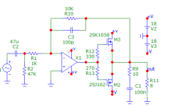
Hi Lineup, I was just curious what a simplified schematic of your design would look like, no disrespect intended. MicroCAP indicates that this simplified schematic seems workable but, haven't tested it practically .
Never-the-less it is an op-amp + 2 Lateral Mosfets, THD and IMD is not too shabby. This is a cheaper, nastier and simpler version than that by Lineup Post 21. Anyone willing to include some simulations pf Lineup's amp they performed, we can compare and discuss what are the mechanisms at work making that in post 21 much better in performance.
The output offset is only about 3 mV in the schematic below since it is balanced by R2 and R10 being equal and no need for additional adjustment. Kindly show us how you derive at a class A amp. To my knowledge if you feed any class A amp with a class B amp signal the output would only be an amplified version of the class B signal including its cross over distortion. Why run it hot? Maybe I am just ignorant. O I forgot the output is less than unity gain, right.


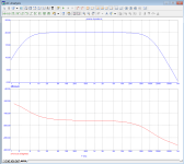
THD still very, very low at 12 milli %. I see no cross-over distortion.

Inter Modulation Distortion of 19 & 20 KHz looks like 0.0001%, no idea why it is measured at these frequencies since it lies outside the audio band but it is what it is.
Never-the-less it is an op-amp + 2 Lateral Mosfets, THD and IMD is not too shabby. This is a cheaper, nastier and simpler version than that by Lineup Post 21. Anyone willing to include some simulations pf Lineup's amp they performed, we can compare and discuss what are the mechanisms at work making that in post 21 much better in performance.
The output offset is only about 3 mV in the schematic below since it is balanced by R2 and R10 being equal and no need for additional adjustment. Kindly show us how you derive at a class A amp. To my knowledge if you feed any class A amp with a class B amp signal the output would only be an amplified version of the class B signal including its cross over distortion. Why run it hot? Maybe I am just ignorant. O I forgot the output is less than unity gain, right.
THD still very, very low at 12 milli %. I see no cross-over distortion.
Inter Modulation Distortion of 19 & 20 KHz looks like 0.0001%, no idea why it is measured at these frequencies since it lies outside the audio band but it is what it is.
Attachments


What exactly are you filtering with 22 Ohm and 470uF? If you are worried about motorboating you don't need the 22 Ohm series resistor the cap alone will do. Op-amps usually have a high PSRR and hum should not be a problem. You throw a hand full of components at a problem that does not exist seems a little illogical to me. Have you practically tested it and found serious hum or what.
Why have bias adjustment when you do not need it, why run the output hot under unnecessary high current only to over spend on the power supply and additional heat sink. It is not smart.
The complexity does not help nor is it impressive to anyone wanting to build it having to spend more bucks under the illusion that they are getting anything better. If al this paraphernalia is necessary then demonstrate that it is.
Was this more on topic?
@Nico Ras
I might try the 2nd of your circuits. The non-inverting with 47k input bias.
You have got me thinking about my circuit.
Thanks 🙂
I might try the 2nd of your circuits. The non-inverting with 47k input bias.
You have got me thinking about my circuit.
Thanks 🙂
This is the 'Choctaw Light'
It works and puts out 10 Watt.

It works and puts out 10 Watt.
Excellent Lineup, if there you encounter a problem expand the design. If not then you are done with a simple clean amplifier and no unnecessary clutter.
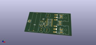
Zoltan, the PCB is equally simple now and everyone can enjoy it. Well done my friend. Between you and Lineup you have introduced a simple clean amplifier design that is both cost effective and well thought out and I will say it will be well received by those in need of it. Lineup, what ideas are you having as a power supply, don't overcomplicate it. Unfortunately there are no dual supply power bricks available. So I guess transformer cap combination. Maybe include a capacitor multiplier of sorts. Well done fellows, may the force be with you. 👍 👍 👍
Zoltan, the PCB is equally simple now and everyone can enjoy it. Well done my friend. Between you and Lineup you have introduced a simple clean amplifier design that is both cost effective and well thought out and I will say it will be well received by those in need of it. Lineup, what ideas are you having as a power supply, don't overcomplicate it. Unfortunately there are no dual supply power bricks available. So I guess transformer cap combination. Maybe include a capacitor multiplier of sorts. Well done fellows, may the force be with you. 👍 👍 👍
Last edited:
Zoltan, what about using surface mount resistors, say 1206 size, still easy to see and handle. They cost nothing and all are 1% some you get at 0.1% but that is overkill. Using SMT may enable you to do a single sided board. Just a thought. Before designing you PCB talk to lineup on the heatsink that is required so that there is no no unnecessary money spent on the guts. I like the fact of each amp having its own power supply caps on board, you may even place a bridge rectifier on each board, Talk to line up what his rectifier requirements are. If the boards turn out fairly inexpensive the DIY folk can spend more money on aesthetics' making it look high-end as well.
Maybe this is asking too much, but how about an equally simple pre-amp that can fit into the same case with all the paraphernalia the members want, Vol, bass, treble and input selector. Who knows this can be a complete desktop product for the DIY folk. I can see myself building one. Heck I have wires running all over the place on my desk.
You know audio folk loves turning knobs. Every time I see a piece of audio I turn a knob, why I don't know.
You know audio folk loves turning knobs. Every time I see a piece of audio I turn a knob, why I don't know.
Last edited:
And for completeness, add a headphone socket with series resistor and you have a complete solution. I hope I am not wandering off topic again Lineup. But I cannot remember a complete integrated amplifier offered on DIYaudio.
Goodness, I am running away with things again. I am thinking placing one of the Chines Bluetooth modules in it and maybe a similar USB to audio converters, I see them on eBay for maybe two dollars. So one analogue input, Bluetooth and USB. This is a complete solution. It would be silly to design either Bluetooth or USB if they can be had for next to nothing.
Once Zoltan completes the boards in consultation with lineup, one of our industrial design members can jump in and create an exotic fron panel and box design using those available on eBay or Ali.
I don't know if Lineup would agree with me but he should only add a complex power supply if there is a problem with what he suggested. You don't try and solve a problem before it exists.Add CRC for better PSRR and output lower ripple.
For example replace 10000uF with 4700uF - 0,22R/5W - 4700uF and add at output RC filter for addition filtering like 1R+470nF and add one 5W resistor from pos to gnd that will fast discharge capacitors when power is switched off.
Hej man.Once Zoltan completes the boards in consultation with lineup, one of our industrial design members can jump in and create an exotic fron panel and box design using those available on eBay or Ali.
Many ideas you have, but let us focus on supply + amplifier.
- Home
- Amplifiers
- Solid State
- Choctaw - 10 Watt Amplifier, 1 Opamp + 2 MOSFET