yep, 120V are more then 94V........but look at the continuous power @4R load: (important for high current amps..i guess)
7293
Table 4 :+/- 29V---> 80W ---> d=1%
3886 Datasheet page 4
+/-28V ---> 60W ---> 0,1%
chris
Yes, but the real advantage is to use it closer to the maximum voltage rating, and use several in parallel. This can achieve quite a high power output and avoid BTL operation while still being able to drive low impedance loads. Two would be good, three would be even better. Above three looks unnecessary.
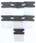
TDA1514A
I had hoped to present test results for this elderly and no longer produced (by Philips/NXP) chip with reputation for good sound.
I made a test-board relying on Fig.4 “Application and test circuit” in the datasheet. All connections were checked with an Ohm-meter before turning the power ON. No load at the output and the input shorted. I used a +/-18V supply and the first TDA1514A chip was destroyed (sound+smoke) immediately after power was turned ON.
I replaced the IC with a similar one after having checked that the output line would not have a low impedance connection to either power rail or ground. Turning the +/-18V supply ON immediately destroyed the second chip with a sound and smoke like the first.
I cut the second chip out leaving a part of the pins in the PCB such that I, without the chip, could check the voltage level on each pin before inserting a third LM1514A. I found no mistake in voltage levels or connections. The third IC was inserted and destroyed immediately on power-ON, like the two before.
I checked my storage of TDA1514A and their origin. I had seven TDA1514A of which three already were destroyed. They were bought in three times from FSXSEMI but all seem to be from the same production lot of which none seem functional. I am 99% certain that the application circuit in Fig.4 is complied with. The supply voltage of +/-18V is much below the limit of +/-25V. The output wasn’t loaded and could accordingly not cause an external current to flow. Thus, the current that caused destruction of the chips had to flow between the two power supply pins (6 and 3). The far most likely reason for destruction is a chip-fault causing high current between pins 6 and 3.
Tomorrow I will try to keep an TDA1514A IC muted and see if the chip is still destroyed. Most likely, those TDA1514A I have are fully non-functional and useless. Sorry maxhifi. At least no-one is tempted to use them for anything. Once more Turbowatch2 was right.
Image 1: The three upper ICs have been destroyed.
Attachments
Hi FF + Turbo
I follow with interest your ideas and i am not really surprised that you plan such a high end amp.😎 modular amp parts is a very good idea . a composite amp like the 1875 is for you not a problem.
sorry i do not want to push you but i really see FF´s triple 1875 module is working but to make a BTL-version i guess its a challenge especially if you plan to do it "modular".
yesterday night i thinking and searching around...
lm3386 module ?
DC+20 28V 68W LM3886 TF HIFI Power Amplifier Board PCB Parallel Bare Board|Instrument Parts & Accessories| | - AliExpress
the LM3886 (TDA7293, 7294) is about 6 euro at digikey. the only chip which is not as strong but cheaper is the TDA7295 - +/-22V 6Apeak ---> 3,36euro
for a high power amp i think you have to use TDA7293 or 7294 or LM3886
this is not really a genuine chip but this price is very interesting:
TZT TDA7293 Digital Audio Amplifier Board Mono Single Channel AC 12v 50V 100W|Integrated Circuits| | - AliExpress
just my 2 cents
chris
Hi Chris,
I will now try to finish the Triple in BTL version.
The modules I mention are not standard modules but modules that are adapted to our particular needs with a custom PCB.
Hi Chris,
I will now try to finish the Triple in BTL version.
😎😎
....
TDA1514A
I had hoped to present test results for this elderly and no longer produced (by Philips/NXP) chip with reputation for good sound.
I made a test-board relying on Fig.4 “Application and test circuit” in the datasheet. All connections were checked with an Ohm-meter before turning the power ON. No load at the output and the input shorted. I used a +/-18V supply and the first TDA1514A chip was destroyed (sound+smoke) immediately after power was turned ON.
I replaced the IC with a similar one after having checked that the output line would not have a low impedance connection to either power rail or ground. Turning the +/-18V supply ON immediately destroyed the second chip with a sound and smoke like the first.
I cut the second chip out leaving a part of the pins in the PCB such that I, without the chip, could check the voltage level on each pin before inserting a third LM1514A. I found no mistake in voltage levels or connections. The third IC was inserted and destroyed immediately on power-ON, like the two before.
I checked my storage of TDA1514A and their origin. I had seven TDA1514A of which three already were destroyed. They were bought in three times from FSXSEMI but all seem to be from the same production lot of which none seem functional. I am 99% certain that the application circuit in Fig.4 is complied with. The supply voltage of +/-18V is much below the limit of +/-25V. The output wasn’t loaded and could accordingly not cause an external current to flow. Thus, the current that caused destruction of the chips had to flow between the two power supply pins (6 and 3). The far most likely reason for destruction is a chip-fault causing high current between pins 6 and 3.
Tomorrow I will try to keep an TDA1514A IC muted and see if the chip is still destroyed. Most likely, those TDA1514A I have are fully non-functional and useless. Sorry maxhifi. At least no-one is tempted to use them for anything. Once more Turbowatch2 was right.
Image 1: The three upper ICs have been destroyed.
The TDA1514A is famous for fakes, and the fakes are famous for behaving like yours did. I read about it on several different forums. Apparently there is a 1990s Marshall guitar amplifier which uses the TDA1514A, and installing a fake has the same result as you had above. Considering that they're from a Chinese supplier, I think it is most likely that your ICs are not genuine at all, because this IC predates the time period of "everything" being Made in China. At least the TDA2030 fakes actually work! It is good you tried!
Last edited:
@maxhifi
you wrote about the Linn Majik I having the TDA1514A.
I´m a bit confused, as I thought the MAJIK I would use the TDA7293 with additional output transistors, what they call (off course!) unique and new "CHAKRA".
Just as fresh as me tomorrow inventing a flat meat ball in a bun, calling it "HAMBurger" and get it patented. Linn would fry the upside first and call it an EDINBurger. Innovation is marketing.
So if you like the sound, it may not be the old Phillips chip?
Last edited:
Why not use BTL configuration? There has never been any disadvantage of BTL sound wise been proofed. It is a nice way to get around high rail voltages and does nothing bad to a signal.
If one amp is fine, the same amp used twice is not worse.
You have to understand the principle: The signal is not processed any different than in the single amp. It only takes the problematic ground connection out of the way.
Some even speculate that non linearity found in the single amp is eliminated.
Bus pumping is impossible, too.
I think most of you will know this page, I like the basic ideas:
DIY BPA300 6x LM3886 300W audio Amplifier
I found not much to criticize on schematic or layout. There is even a finished PCB around.
You can build a pair and use it it in 3x parallel mode at maximum voltage (maybe with SMPS ?).
Later you can can build a second pair and use for bi.amping or even convert to the bridged version.
Alternative, if for some reason you don´t like the sound any more, use a pair bridged as an Subwoofer amp. It has lots of ampere and damping for any woofer.
Sorry FF if I´m a little too practical, too fast. I´m at the personal point to build my last A/B amp, as it´s era is ending. The LM3886 is the last high end compatible chip amp that will be available for, hopefully, a few years in non fake version. Anyway, I will screw a few spare chips into the case if I build it, just beside the printed schematic.
Last edited:
@maxhifi
you wrote about the Linn Majik I having the TDA1514A.
I´m a bit confused, as I thought the MAJIK I would use the TDA7293 with additional output transistors, what they call (off course!) unique and new "CHAKRA".
Just as fresh as me tomorrow inventing a flat meat ball in a bun, calling it "HAMBurger" and get it patented. Linn would fry the upside first and call it an EDINBurger. Innovation is marketing.
So if you like the sound, it may not be the old Phillips chip?
Linn likes to recycle names. You are indeed correct about the newer Majik-I, but the one I own is the original version from 1994, and has two parallel TDA1514A per channel, and a regulated power supply. The transistors on either end of the ICs are for regulating the positive and negative rails.
It is a straightforward design, but has nice attention to detail: each IC has a servo to eliminate offset, and the pair are gain matched by a trimmer which is sealed at the factory. The regulated power supply I also believe helps the IC achieve its potential, and using two reduces the current and therefore distortion. Basically just normal design setting the TDA1514A up for success, not any magic, despite the name.
Attachments

Last edited:
OK, I see. The 1514A might be a nice chip, but hunting for one that works might only bring up some pin compatible chip, with a totally different die inside. The Chinese faker is really creative in producing worthless junk from valuable raw material.
Found the fire cracker FF is using, even with "matching numbers":
1pcs/lot TDA1514A TDA1514 ZIP 9 50W In Stock 50 W high performance hi fi amplifier|Performance Chips| | - AliExpress
The TDA7293 is not easily compared to the LM3886. It is a quite different concept. Have a look at both data sheets. The suggested ways of paralleling the chips are very different. The "high power" option with external transistors is not very elegant. It makes the use of MOS transistor stages inside the chip seem questionable, if you extend them with bipolar ones. I do not expect very high end sound from such an combination.
It´s "advantage" to allow higher supply voltages is none, as you are limited by the heat transfer, chip to heat sink. Except you want to use 16 Ohm speaker.
To me it seems more a nice chip for OEM solutions, where you might use it to cut cost´s.
As I mentioned, the A/B stuff is dying out faster than the dinosaur´s. Getting harder to find something that is going to stay and no new development any more.
All Bruno´s fault. Shame on him!
OK, I see. The 1514A might be a nice chip, but hunting for one that works might only bring up some pin compatible chip, with a totally different die inside. The Chinese faker is really creative in producing worthless junk from valuable raw material.
Found the fire cracker FF is using, even with "matching numbers":
1pcs/lot TDA1514A TDA1514 ZIP 9 50W In Stock 50 W high performance hi fi amplifier|Performance Chips| | - AliExpress
The TDA7293 is not easily compared to the LM3886. It is a quite different concept. Have a look at both data sheets. The suggested ways of paralleling the chips are very different. The "high power" option with external transistors is not very elegant. It makes the use of MOS transistor stages inside the chip seem questionable, if you extend them with bipolar ones. I do not expect very high end sound from such an combination.
It´s "advantage" to allow higher supply voltages is none, as you are limited by the heat transfer, chip to heat sink. Except you want to use 16 Ohm speaker.
To me it seems more a nice chip for OEM solutions, where you might use it to cut cost´s.
As I mentioned, the A/B stuff is dying out faster than the dinosaur´s. Getting harder to find something that is going to stay and no new development any more.
All Bruno´s fault. Shame on him!
I agree totally about MOS devices being questionable. My comment about the higher voltage limit being useful assumes multiple parallel devices, to limit the current each device is delivering to within ratings. For one single IC and a normal 8 ohm speaker I agree it is of little consequence. I also do not like the design with the so called helper transistors - why not just build a fully discrete amp in this case? Maybe you are right that the 3886 is the best on the market,
I think you're also correct that it is likely not worth it to hunt for obsolete parts, or make a new design using them. It really amazes me how much trouble the Chinese companies go to to make fakes, and in this case sadly just junk. I was hopeful that FF would have luck with those 1514A, it is too bad it ended up being junk.
What is wrong with hybrid designs? The goal of such designs is often of taking advantage of different technologies. So, in the case of an amplifier, the input and VAS would take the form of an IC, and the driver and power stages would be discrete.maxhifi said:I also do not like the design with the so called helper transistors - why not just build a fully discrete amp in this case?
The TDA7293 is not easily compared to the LM3886. It is a quite different concept. Have a look at both data sheets. The suggested ways of paralleling the chips are very different. The "high power" option with external transistors is not very elegant. It makes the use of MOS transistor stages inside the chip seem questionable, if you extend them with bipolar ones. I do not expect very high end sound from such an combination.
Why not? If I get it right, the circuitry at p. 13 in the Signetics Thompson datasheet is an example of a class G amplifier with modulated higher rails (or do we call it class H?). That's not too uncommon. At lower listening levels only the chip is active.
My idea would be a combination of all three options: Paralleling two or three chips (as per p. 14), class G (as per p.13, but with more powerful external transistors, maybe MOSFETs instead of those venerable darlingtons), and BTL (not documented in the DS, external phase inversion needed). At 50-25-0-25-50 Vdc rails this would result in a very high power, though compact and efficient amplifier.
Best regards!
What is wrong with hybrid designs? The goal of such designs is often of taking advantage of different technologies. So, in the case of an amplifier, the input and VAS would take the form of an IC, and the driver and power stages would be discrete.
The main reason why I would be biased against a hybrid design using a special amplifier driver IC, is that over time, ICs can be discontinued, and discontinued ICs become difficult to substitute. This could end up turning the entire amplifier into a boat anchor years into the future. Functional substitutes can almost always be found for just about any discrete transistors on the other hand. If this is actually an important consideration or not depends on the priorities of the builder.
I do not have a final favorite whit all these amp chips, even as one of them seems to be in the front row.
With the chip amps that are still available, the theoretic judgement which one is the best, is a discussion with open end. Personally, I try to find the most promising one for a project. One of my mantra´s is, the most complicated amp never is the best. How much extra components are needed and what is "gimmick" is not easy to decide on.
The ideas about it may be very different. In my thinking, if a chip amp does not sound good in bare form, any add on will not make it a singer.
In the end only the finally build amp in your room compared in a listening test will decide what is best. So there are limits to the theoretical examination.
As an engineer I do not expect an amp, that measures bad, to sound good.
As an audiophile I have learned that amps, that measure very good, do not have to sound good.
The last, maybe 15, years have made it much simpler to find good sounding, cheap amp concepts. For me the once 2nd class chip amp, may it be A/B or D, has become the most attractive.
I have quite some different amps at home to compare "sound" and some amps that had a good reputation in their time just loose against today´s average amps.
Maybe a short description for "good sound" with an amplifier?
It means to me that if you use the same components at the same loudspeaker with the same program and change only the amp, there are no parts of the reproduction that start to sound wrong. Compared to a reference amp. Ignoring that a 25W amp may not have the same, brute force in the lower octave. This is the subjective, not measurable part of music reproduction that matters most for me.
30 years ago you could do this test in a few minutes and decide which amp was better. Today, with even cheap amps, things have gotten much more complicated.
TDA1514A
I continued a bit the testing of my TDA1514A samples without bootstrapping connected.
One specimen blew when the +/-18V supply voltage was applied.
Two other specimens did not appear to “burn” such as the four other but did not show any important reaction to supply voltage or an input signal.
One did put its output voltage close to zero but a sine-wave at the input caused no signal at the output.
Another specimen put the output voltage at around -12V. It did not react to a sine-wave at the input.
Having tested 6 out of my 7 TDA1514A ICs, and knowing from maxhifi that there are many fakes around and no supply of genuine items possible from reputed suppliers, I find it time to conclude that TDA1514A ICs bought from Asia are very likely useless. They will hardly perform even to a reduced level. Worst case they self-destruct when supply voltage is applied, best case they do not react much at all.
I terminate my testing of TDA1514A.
@FF
I´m really sorry you verified my worst expectations. I was surprised when I saw your chips still offered a dozen times at Aliexpress, all with your serial and production numbers. Which is impossible. The faker not even changed numbers after a few thousand pieces and years.
Maybe you got fakes that failed quality control 🙁
At least, in the sense of Chinese mentality they worked: You paid in valuable Euros for worthless Wuhan´s and you are unable to complain!
I expected most of them to be fake, but basically working. Maybe your design misses some tweak to let them live. If you wanted to know for sure, I would order one of the cheap kit´s with such a fake TDA1514A, as some seem to work if you look at the comments.
In my thinking, the ones you got are the best outcome, imagine they would work, you use them for a project and the resulting sound is bad, after you spent all this time and money to build an amp. You would be disappointed and think you constructed something wrong. In reality it was just because your chip was something cheap and different inside.
I start to understand why the Chinese designers fit these (theoretical) unnecessary "Speaker Protections" to the amp boards...
It's impossible to argue with that....
As an engineer I do not expect an amp, that measures bad, to sound good.
As an audiophile I have learned that amps, that measure very good, do not have to sound good.
...
@FF
I´m really sorry you verified my worst expectations. I was surprised when I saw your chips still offered a dozen times at Aliexpress, all with your serial and production numbers. Which is impossible. The faker not even changed numbers after a few thousand pieces and years.
Maybe you got fakes that failed quality control 🙁
At least, in the sense of Chinese mentality they worked: You paid in valuable Euros for worthless Wuhan´s and you are unable to complain!
I expected most of them to be fake, but basically working. Maybe your design misses some tweak to let them live. If you wanted to know for sure, I would order one of the cheap kit´s with such a fake TDA1514A, as some seem to work if you look at the comments.
In my thinking, the ones you got are the best outcome, imagine they would work, you use them for a project and the resulting sound is bad, after you spent all this time and money to build an amp. You would be disappointed and think you constructed something wrong. In reality it was just because your chip was something cheap and different inside.
I start to understand why the Chinese designers fit these (theoretical) unnecessary "Speaker Protections" to the amp boards...
I was thinking about those kits too. I also looked through the Philips semiconductor handbook to see if there are other comparable ICs, with different names. The answer is not really.
It is surprising to me how it is almost always possible to track down 70 year old vacuum tubes, but a 20 year old IC is absolutely unobtainable.
The 6L6 tube was introduced in 1936 and is still in production 84 years later, albeit not by the original manufacturer.
Best regards!
Best regards!
- Home
- Amplifiers
- Chip Amps
- Chip-amps suited as power stage in a composite amplifier, LM1875/TDA2050 excluded.