OPA549, TDA7265B, TDA7292 and genuine LM1875.
In posting #45 I wrote that I intended to test the OPA549, being a power OP-AMP intended to work with gains at least down to unity. Buying OPA549 was not as easy as expected.
Many distributors do no longer keep OPA549 as stock. I finally found a couple on a European site from an international distributor. I ordered two, adding to a total price a little above the minimum order for free delivery. One and a half week later, a kind delivery man appeared offering me the parcel against a further payment of 60%. Why? Because the ICs were apparently not on stock in Europe and my order had been turned into an import order from the US (with me to pay the costs for the import). With efficient help from PayPal and cooperation from the distributor, the order was canceled but no ICs.
As a European buyer, make sure that if the goods are not on stock in Europe, your order is not turned into buyers cost import from the US.
I had to find a European supplier with OPA549 on stock. The choice is very limited but I finally realized that Farnell is a UK registered company (European Community trade rules apply until 2021 / real Brexit) with continental subsidiaries. I ordered at Farnell (paying only VAT) and short after I received OPA549, TDA7265B (an improved version of TDA7265), TDA7292 (TDA7265 on steroids) and genuine LM1875. All well protected from static discharges as it was common in the past. As I anyway had to order OPA549 for test, I added the TDA7265B with the hope that the current limiter works better than for the ordinary TDA7265 and the TDA7292 being curious if the 2x5A current limits can be used in practice. Finally, I got genuine LM1875, which is not that easy. I had many LM1875 ICs already but hardly one that could trusted as behaving like a fully genuine.
These chip-amps will be tested soon when I have finished with my triple LM1875 (“fake”) amplifier in BTL version (six LM1875 per channel).
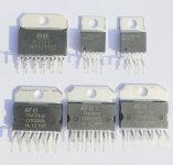
Image: Genuine OPA549T, TDA7265B, TDA7292 and LM1875, supplied by Farnell, to be used as reference for others fearing that what they have is not genuine.
Turbowatch2 and Nigel are right – it is a good feeling when you can rely on datasheet performance.
In posting #45 I wrote that I intended to test the OPA549, being a power OP-AMP intended to work with gains at least down to unity. Buying OPA549 was not as easy as expected.
Many distributors do no longer keep OPA549 as stock. I finally found a couple on a European site from an international distributor. I ordered two, adding to a total price a little above the minimum order for free delivery. One and a half week later, a kind delivery man appeared offering me the parcel against a further payment of 60%. Why? Because the ICs were apparently not on stock in Europe and my order had been turned into an import order from the US (with me to pay the costs for the import). With efficient help from PayPal and cooperation from the distributor, the order was canceled but no ICs.
As a European buyer, make sure that if the goods are not on stock in Europe, your order is not turned into buyers cost import from the US.
I had to find a European supplier with OPA549 on stock. The choice is very limited but I finally realized that Farnell is a UK registered company (European Community trade rules apply until 2021 / real Brexit) with continental subsidiaries. I ordered at Farnell (paying only VAT) and short after I received OPA549, TDA7265B (an improved version of TDA7265), TDA7292 (TDA7265 on steroids) and genuine LM1875. All well protected from static discharges as it was common in the past. As I anyway had to order OPA549 for test, I added the TDA7265B with the hope that the current limiter works better than for the ordinary TDA7265 and the TDA7292 being curious if the 2x5A current limits can be used in practice. Finally, I got genuine LM1875, which is not that easy. I had many LM1875 ICs already but hardly one that could trusted as behaving like a fully genuine.
These chip-amps will be tested soon when I have finished with my triple LM1875 (“fake”) amplifier in BTL version (six LM1875 per channel).
Image: Genuine OPA549T, TDA7265B, TDA7292 and LM1875, supplied by Farnell, to be used as reference for others fearing that what they have is not genuine.
Turbowatch2 and Nigel are right – it is a good feeling when you can rely on datasheet performance.
Attachments
Last edited:
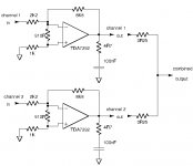
TDA7265B
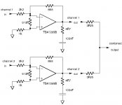
The version of TDA7265 with improved performance, the TDA7265B, was given a short test mainly to see if the current limiter performed better than for the ordinary TDA7265. This TDA7265B IC was genuine and bought at Farnell.
The TDA7265B was arranged in an inverting configuration with a gain of -4 (2K2/8K8).
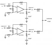
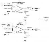
Image 1: Essential components of the test circuit.
For the further tests, a regulated supply of +/-26V was used. A load of 4 Ohm was connected such that the current limit could be reached for individual channels. 910 Ohm resistors were connected between the input pins of the TDA7265B in order to improve stability.
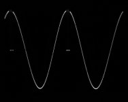
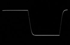
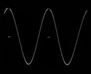
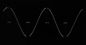
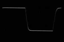
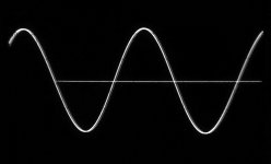
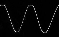
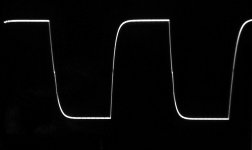
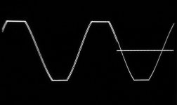
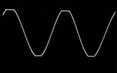
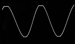
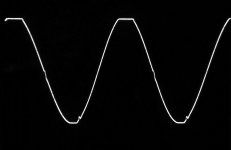
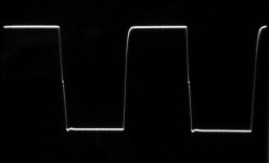
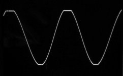
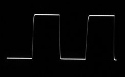
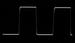
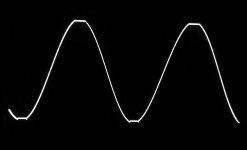
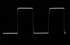
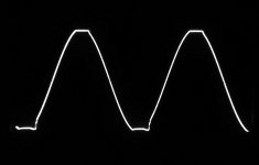
Image 2: Square-wave response at 20KHz, 20Vpp in 4 Ohm, channel 1.
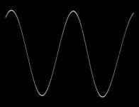
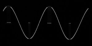
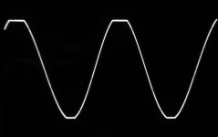
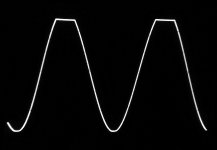
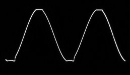
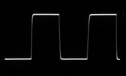
Image 3: Sine-wave current clipping at 1KHz, 40Vpp in 4 Ohm, channel 1.
Image 4: Square-wave response at 20KHz, 20Vpp in 4 Ohm, channel 2.
Image 5: Sine-wave current clipping at 1KHz, 40Vpp in 4 Ohm, channel 2.
Current clipping load-release spikes started at 19V (peak) in 4 Ohm, thus at 4.7A (peak). The TDA7265B datasheet states two current limiter values – one under “Absolute maximum ratings” of 5A and one under “Electrical characteristics” of 4A (typical). One could ask about the relevance of the 5A if the internal current limiter will be activated around 4A. 4A must be the valid value such that the actual 4.7A well exceeds the datasheet indication.
For the ordinary TDA7265, only a value of 4.5A is given under “Absolute maximum ratings”. In posting #49, the current limiter value was found to be some 3.75A for each individual channel. Initially assuming 4.5A, 3.75A is somewhat disappointing. As TDA7265B is an improved version of the TDA7265, it is unlikely that the current limiter value for the ordinary TDA7265 is higher than for the TDA7265B. But, the TDA7265 datasheet shows no current limiter value under “Electrical characteristics”. The ordinary TDA7265 performance has to be seen in that light. The value of 3.75A, found in posting #49, seems realistic.
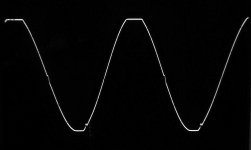
The two channels were then combined into a single channel using two 0.25 Ohm power resistors.
For that combined channel, it was necessary to reduce the load impedance in order to increase the load current such that current limiting could be reached. For a start, the load impedance was reduced to 2.7 Ohm.
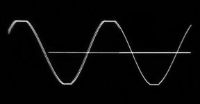
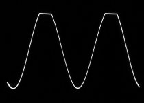
Image 6: Sine-wave at 1KHz, voltage clipping at 42Vpp in 2.7 Ohm, combined channel.
Hence, 7.7A (peak) was handled without signs of current clipping.
The load impedance was reduced further to 2 Ohm.
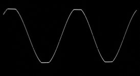
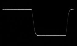
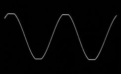
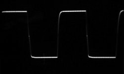
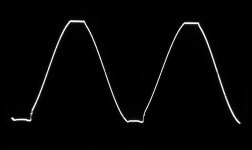
Image 7: Sine-wave at 1KHz, 35Vpp in 2 Ohm, combined channel, at start.
Image 8: Sine-wave at 1KHz, current clipping at 35Vpp in 2 Ohm, combined channel, after around 2 seconds.
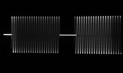
When a 35Vpp sine-wave signal was started, no current limiting was observed right from a start. But after around 2 seconds, current clipping load-release spikes appeared. 35Vpp in 2 ohm means 8.7A (peak). 8.7A is absolutely a respectable value for a single IC. Unfortunately, current clipping is the same way as for the ordinary TDA7265 using clipping load-release spikes that are likely to generate a very high level of harmonics. For that reason, current clipping should certainly be avoided. Using spike-type load-release current limiting is unfortunate when two channels are combined. When the weakest channel reaches its limit and generates a spike by dropping the load current for a short moment, the stronger channel is suddenly loaded with the full load current and will also reach its limit. Thus, this type of current limiting reaches the combined limit when the weakest channel reaches its limit. This is not ideal.
Next test is of the TDA7292. It is hoped that current limiting is through maintaining of the limit current and not through current limiting load-release spikes such as for the TDA7265(B).
The version of TDA7265 with improved performance, the TDA7265B, was given a short test mainly to see if the current limiter performed better than for the ordinary TDA7265. This TDA7265B IC was genuine and bought at Farnell.
The TDA7265B was arranged in an inverting configuration with a gain of -4 (2K2/8K8).
Image 1: Essential components of the test circuit.
For the further tests, a regulated supply of +/-26V was used. A load of 4 Ohm was connected such that the current limit could be reached for individual channels. 910 Ohm resistors were connected between the input pins of the TDA7265B in order to improve stability.
Image 2: Square-wave response at 20KHz, 20Vpp in 4 Ohm, channel 1.
Image 3: Sine-wave current clipping at 1KHz, 40Vpp in 4 Ohm, channel 1.
Image 4: Square-wave response at 20KHz, 20Vpp in 4 Ohm, channel 2.
Image 5: Sine-wave current clipping at 1KHz, 40Vpp in 4 Ohm, channel 2.
Current clipping load-release spikes started at 19V (peak) in 4 Ohm, thus at 4.7A (peak). The TDA7265B datasheet states two current limiter values – one under “Absolute maximum ratings” of 5A and one under “Electrical characteristics” of 4A (typical). One could ask about the relevance of the 5A if the internal current limiter will be activated around 4A. 4A must be the valid value such that the actual 4.7A well exceeds the datasheet indication.
For the ordinary TDA7265, only a value of 4.5A is given under “Absolute maximum ratings”. In posting #49, the current limiter value was found to be some 3.75A for each individual channel. Initially assuming 4.5A, 3.75A is somewhat disappointing. As TDA7265B is an improved version of the TDA7265, it is unlikely that the current limiter value for the ordinary TDA7265 is higher than for the TDA7265B. But, the TDA7265 datasheet shows no current limiter value under “Electrical characteristics”. The ordinary TDA7265 performance has to be seen in that light. The value of 3.75A, found in posting #49, seems realistic.
The two channels were then combined into a single channel using two 0.25 Ohm power resistors.
For that combined channel, it was necessary to reduce the load impedance in order to increase the load current such that current limiting could be reached. For a start, the load impedance was reduced to 2.7 Ohm.
Image 6: Sine-wave at 1KHz, voltage clipping at 42Vpp in 2.7 Ohm, combined channel.
Hence, 7.7A (peak) was handled without signs of current clipping.
The load impedance was reduced further to 2 Ohm.
Image 7: Sine-wave at 1KHz, 35Vpp in 2 Ohm, combined channel, at start.
Image 8: Sine-wave at 1KHz, current clipping at 35Vpp in 2 Ohm, combined channel, after around 2 seconds.
When a 35Vpp sine-wave signal was started, no current limiting was observed right from a start. But after around 2 seconds, current clipping load-release spikes appeared. 35Vpp in 2 ohm means 8.7A (peak). 8.7A is absolutely a respectable value for a single IC. Unfortunately, current clipping is the same way as for the ordinary TDA7265 using clipping load-release spikes that are likely to generate a very high level of harmonics. For that reason, current clipping should certainly be avoided. Using spike-type load-release current limiting is unfortunate when two channels are combined. When the weakest channel reaches its limit and generates a spike by dropping the load current for a short moment, the stronger channel is suddenly loaded with the full load current and will also reach its limit. Thus, this type of current limiting reaches the combined limit when the weakest channel reaches its limit. This is not ideal.
Next test is of the TDA7292. It is hoped that current limiting is through maintaining of the limit current and not through current limiting load-release spikes such as for the TDA7265(B).
Attachments
-
 TDA7265B_0R25_1KHz_35Vpp_2Ohm_26V_2.jpg313.3 KB · Views: 134
 -
 TDA7265B_0R25_1KHz_35Vpp_2Ohm_26V_1.jpg330.9 KB · Views: 105
 -
 TDA7265B_0R25_1KHz_42Vpp_2.7Ohm_26V.jpg203.4 KB · Views: 102
 -
 TDA7265B_Ch2_1KHz_40Vpp_4Ohm_26V.jpg248.3 KB · Views: 107
 -
 TDA7265B_Ch2_20KHz_20Vpp_4Ohm_26V.jpg211.5 KB · Views: 449
 -
 TDA7265B_Ch1_1KHz_40Vpp_4Ohm_26V.jpg246.8 KB · Views: 437
 -
 TDA7265B_Ch1_20KHz_20Vpp_4Ohm_26V.jpg217.2 KB · Views: 525
 -
 TDA7265BTest.jpg50.4 KB · Views: 545
TDA7292
TDA7292, with identical pin-layout as TDA7265(B), was given a short test mainly to see if the current limiter performed better than for the TDA7265(B) and without load-release spikes. The TDA7292 IC used was genuine and bought at Farnell.
The TDA7292 was arranged in an inverting configuration with a gain of -4 (2K2/8K8).
Image 1: Essential components of the test circuit.
For the following tests, a regulated supply of +/-26V was used. A load of 4 Ohm was connected such that the current limit could be reached for an individual channel. 910 Ohm resistors were connected between the input pins of the TDA7292 in order to improve stability.
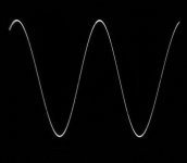
Image 2: Square-wave response at 20KHz, 20Vpp in 4 Ohm, channel 1.
Image 3: Sine-wave current clipping at 1KHz, 40Vpp in 4 Ohm, channel 1.
Image 4: Square-wave response at 20KHz, 20Vpp in 4 Ohm, channel 2.
Image 5: Sine-wave current clipping at 1KHz, 40Vpp in 4 Ohm, channel 2.
Current clipping load-release spikes started at 19V (peak) in 4 Ohm, thus at 4.7A (peak). The TDA7292 datasheet states two current limiter values – one under “Absolute maximum ratings” of 5A and one under “Electrical performance” of equally 5A (typical). 4.7A is the same value as obtained for the TDA7265B and on the low side of the 5A indicated in the datasheet. Also the square-wave response at 20KHz is very similar to that of the TDA7265B.
Unfortunately, current clipping is implemented the same way as for the ordinary TDA7265 and the TDA7265B, using load-release spikes that are likely to generate a very high level of harmonics.
The two channels were following combined into a single channel using two 0.25 Ohm power resistors.
For that combined channel, it was necessary to reduce the load impedance in order to increase the load current such that current limiting could be reached. For a start, the load impedance was reduced to 2.7 Ohm.
Image 6: Sine-wave at 1KHz, voltage clipping at 42Vpp in 2.7 Ohm, combined channel.
Hence, 7.7A (peak) was handled without signs of current clipping.
The load impedance was reduced further to 2 Ohm.
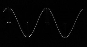
Image 7: Sine-wave at 1KHz, 36Vpp in 2 Ohm, combined channel, at the very start.
Image 8: Sine-wave at 1KHz, current clipping at 36Vpp in 2 Ohm, combined channel, after around 1 second.
When a 36Vpp sine-wave signal was started, no current limiting was observed at the very start. But after just 1 second, current clipping load-release spikes appeared. 36Vpp in 2 Ohm means around 9A (peak). The performance of the TDA7292 was very similar to that of the TDA7265B. Unfortunately also for the current clipping using load-release spikes that are likely to generate a very high level of harmonics. For that reason, current clipping should definitely be avoided.
Next test may be of the OPA549T. It is a bit more work as I have no test PCB and need to implement the circuit on a Vero-board.
TDA7292, with identical pin-layout as TDA7265(B), was given a short test mainly to see if the current limiter performed better than for the TDA7265(B) and without load-release spikes. The TDA7292 IC used was genuine and bought at Farnell.
The TDA7292 was arranged in an inverting configuration with a gain of -4 (2K2/8K8).
Image 1: Essential components of the test circuit.
For the following tests, a regulated supply of +/-26V was used. A load of 4 Ohm was connected such that the current limit could be reached for an individual channel. 910 Ohm resistors were connected between the input pins of the TDA7292 in order to improve stability.
Image 2: Square-wave response at 20KHz, 20Vpp in 4 Ohm, channel 1.
Image 3: Sine-wave current clipping at 1KHz, 40Vpp in 4 Ohm, channel 1.
Image 4: Square-wave response at 20KHz, 20Vpp in 4 Ohm, channel 2.
Image 5: Sine-wave current clipping at 1KHz, 40Vpp in 4 Ohm, channel 2.
Current clipping load-release spikes started at 19V (peak) in 4 Ohm, thus at 4.7A (peak). The TDA7292 datasheet states two current limiter values – one under “Absolute maximum ratings” of 5A and one under “Electrical performance” of equally 5A (typical). 4.7A is the same value as obtained for the TDA7265B and on the low side of the 5A indicated in the datasheet. Also the square-wave response at 20KHz is very similar to that of the TDA7265B.
Unfortunately, current clipping is implemented the same way as for the ordinary TDA7265 and the TDA7265B, using load-release spikes that are likely to generate a very high level of harmonics.
The two channels were following combined into a single channel using two 0.25 Ohm power resistors.
For that combined channel, it was necessary to reduce the load impedance in order to increase the load current such that current limiting could be reached. For a start, the load impedance was reduced to 2.7 Ohm.
Image 6: Sine-wave at 1KHz, voltage clipping at 42Vpp in 2.7 Ohm, combined channel.
Hence, 7.7A (peak) was handled without signs of current clipping.
The load impedance was reduced further to 2 Ohm.
Image 7: Sine-wave at 1KHz, 36Vpp in 2 Ohm, combined channel, at the very start.
Image 8: Sine-wave at 1KHz, current clipping at 36Vpp in 2 Ohm, combined channel, after around 1 second.
When a 36Vpp sine-wave signal was started, no current limiting was observed at the very start. But after just 1 second, current clipping load-release spikes appeared. 36Vpp in 2 Ohm means around 9A (peak). The performance of the TDA7292 was very similar to that of the TDA7265B. Unfortunately also for the current clipping using load-release spikes that are likely to generate a very high level of harmonics. For that reason, current clipping should definitely be avoided.
Next test may be of the OPA549T. It is a bit more work as I have no test PCB and need to implement the circuit on a Vero-board.
Attachments
-
 TDA7292_1KHz_CurClip36Vpp_2Ohm_26V_2.jpg340.2 KB · Views: 101
 -
 TDA7292_1KHz_36Vpp_2Ohm_26V_1.jpg370.7 KB · Views: 109
 -
 TDA7292_1KHz_Clip42Vpp_2.7Ohm_26V.jpg230.7 KB · Views: 92
 -
 TDA7292_Ch2_1KHz_CurClip40Vpp_4Ohm_26V.jpg318.3 KB · Views: 92
 -
 TDA7292_Ch2_20KHz_20Vpp_4Ohm_26V.jpg393.1 KB · Views: 96
 -
 TDA7292_Ch1_1KHz_CurClip40Vpp_4Ohm_26V.jpg478.6 KB · Views: 90
 -
 TDA7292_Ch1_20KHz_20Vpp_4Ohm_26V.jpg311.2 KB · Views: 127
 -
 TDA7292Test.jpg50.1 KB · Views: 139
Thank you FF for your investigation.🙂
yes the TDA7265B and the TDA7292 are very similar. the Datasheet show not always at the same test specification and therefore the compare is not easy but at some power and THD diagrams TDA7292 looks better. the price for both per 1 pcs is about 3,92 at digikey. so its the same.
chris
yes the TDA7265B and the TDA7292 are very similar. the Datasheet show not always at the same test specification and therefore the compare is not easy but at some power and THD diagrams TDA7292 looks better. the price for both per 1 pcs is about 3,92 at digikey. so its the same.
chris
OPA549(T)
OPA549 is the only chip-amp I have tested here that is specified in the datasheet to be stable at unity gain. OPA549 is not presented as an audio amplifier but as a power OP-AMP to be used for various purposes, including audio use. Different versions of such power OP-AMPs exist from Burr Brown (TI) but the OPA549 and the OPA541 are the only versions with characteristics sufficient to supply medium power audio. OPA549 can handle up to 8A output current and +/-30V supply according to the datasheet. OPA541 can handle only 5A. OPA549 is designed with two pins for the output terminal and for both power supply terminals. This indicates serious performance as the current handling is improved. A drawback of the OPA549 is the price some 3-4 times that of an LM3886 IC.
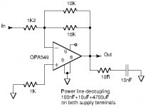
Image 1: Essential components in the OPA549 test circuit. Very low impedance connections were used to connect the circuit components.
One 10K feedback resistor was used for a gain of -8 (inverting). For a gain of -4, two 10K feedback resistors were used in parallel.
Using a +/-26V regulated power supply, an 8 Ohm load and configured for a gain of -8, first tests were conducted.
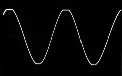
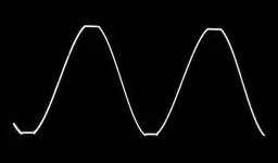
Image 2: 1KHz sine-wave (voltage) clipping at 47Vpp in 8 Ohm.
Image 3: 20KHz square-wave at 20Vpp.
Image 4: Sine-wave at 20KHz, (voltage) clipping at 47Vpp in 8 Ohm.
The offset voltage at the output was measured to 3.6mV.
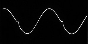
As can be seen from Image 4, cross-over deformation can is noticeable at 20KHz. The frequency content of that cross-over deformation is (first order) located above the audible band. The square-wave reproduction hints a rather slow amplifier which could be the reason it remains stable even at low closed loop gain. With a 4Vpp signal, the -3dB bandwidth was found to be some 90KHz, which is pretty low indeed.
Image 5: 90KHz sine-wave at 3Vpp (-3dB limit).
At the -3dB limit of 90KHz, the cross-over deformation is very visible.
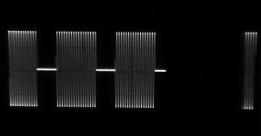
Problems appeared when a 4 Ohm load was used. Increasing the signal amplitude in a 4 Ohm load quickly left the OPA549 to perform repeated, seemingly temperature dependent, shut-downs. The repeated shut-down periods were in the order of 5ms.
Image 6: Recurrent thermal shut-downs shown using a 5ms/div timebase on the oscilloscope.
Image 7: Recurrent thermal shut-downs shown using a 10ms/div timebase on the oscilloscope.
Such recurrent thermal shut-downs are likely to sound poor as the harmonics generated will be substantial.
The OPA549 IC heated up fast and what appeared to be a temperature protection feature intervened particularly fast. My impression was that the intervention was quicker than for other chip-amps I have tested.
The OPA549 IC was for a start insulated from the aluminum cooling profile using a thermally conductive silicone pad. The silicone pad was subsequently removed.
Image 8: OPA549T IC with insulating silicone pad.
With the insulating silicone pad removed, tests using a 4 Ohm load could be conducted. Even without the silicone pad and with the IC cooling tap firmly clamped to the aluminum cooling profile, interference from thermal protection showed-up very fast when the load impedance was reduced further.
Image 9: 1KHz sine-wave, (voltage) clipping at 41Vpp in 2.7 Ohm.
Image 10: 1KHz sine-wave, current clipping at 37Vpp in 2 Ohm.
37Vpp in 2 Ohm means 9.2A peak which is within the specifications in the datasheet. As can be seen from images 9 and 10, recurrent thermal shut-down periods already appeared short after start. For use near it maximum current handling capacity, the OPA549 is very dependent on immaculate thermal contact to a cooling structure.
Sensitivity to capacitive loading at the output of the OPA549 was tested. 1uF appeared to be about the limit for stability.
To be continued with lower gains in a subsequent posting………...
OPA549 is the only chip-amp I have tested here that is specified in the datasheet to be stable at unity gain. OPA549 is not presented as an audio amplifier but as a power OP-AMP to be used for various purposes, including audio use. Different versions of such power OP-AMPs exist from Burr Brown (TI) but the OPA549 and the OPA541 are the only versions with characteristics sufficient to supply medium power audio. OPA549 can handle up to 8A output current and +/-30V supply according to the datasheet. OPA541 can handle only 5A. OPA549 is designed with two pins for the output terminal and for both power supply terminals. This indicates serious performance as the current handling is improved. A drawback of the OPA549 is the price some 3-4 times that of an LM3886 IC.
Image 1: Essential components in the OPA549 test circuit. Very low impedance connections were used to connect the circuit components.
One 10K feedback resistor was used for a gain of -8 (inverting). For a gain of -4, two 10K feedback resistors were used in parallel.
Using a +/-26V regulated power supply, an 8 Ohm load and configured for a gain of -8, first tests were conducted.
Image 2: 1KHz sine-wave (voltage) clipping at 47Vpp in 8 Ohm.
Image 3: 20KHz square-wave at 20Vpp.
Image 4: Sine-wave at 20KHz, (voltage) clipping at 47Vpp in 8 Ohm.
The offset voltage at the output was measured to 3.6mV.
As can be seen from Image 4, cross-over deformation can is noticeable at 20KHz. The frequency content of that cross-over deformation is (first order) located above the audible band. The square-wave reproduction hints a rather slow amplifier which could be the reason it remains stable even at low closed loop gain. With a 4Vpp signal, the -3dB bandwidth was found to be some 90KHz, which is pretty low indeed.
Image 5: 90KHz sine-wave at 3Vpp (-3dB limit).
At the -3dB limit of 90KHz, the cross-over deformation is very visible.
Problems appeared when a 4 Ohm load was used. Increasing the signal amplitude in a 4 Ohm load quickly left the OPA549 to perform repeated, seemingly temperature dependent, shut-downs. The repeated shut-down periods were in the order of 5ms.
Image 6: Recurrent thermal shut-downs shown using a 5ms/div timebase on the oscilloscope.
Image 7: Recurrent thermal shut-downs shown using a 10ms/div timebase on the oscilloscope.
Such recurrent thermal shut-downs are likely to sound poor as the harmonics generated will be substantial.
The OPA549 IC heated up fast and what appeared to be a temperature protection feature intervened particularly fast. My impression was that the intervention was quicker than for other chip-amps I have tested.
The OPA549 IC was for a start insulated from the aluminum cooling profile using a thermally conductive silicone pad. The silicone pad was subsequently removed.
Image 8: OPA549T IC with insulating silicone pad.
With the insulating silicone pad removed, tests using a 4 Ohm load could be conducted. Even without the silicone pad and with the IC cooling tap firmly clamped to the aluminum cooling profile, interference from thermal protection showed-up very fast when the load impedance was reduced further.
Image 9: 1KHz sine-wave, (voltage) clipping at 41Vpp in 2.7 Ohm.
Image 10: 1KHz sine-wave, current clipping at 37Vpp in 2 Ohm.
37Vpp in 2 Ohm means 9.2A peak which is within the specifications in the datasheet. As can be seen from images 9 and 10, recurrent thermal shut-down periods already appeared short after start. For use near it maximum current handling capacity, the OPA549 is very dependent on immaculate thermal contact to a cooling structure.
Sensitivity to capacitive loading at the output of the OPA549 was tested. 1uF appeared to be about the limit for stability.
To be continued with lower gains in a subsequent posting………...
Attachments
-
 OPA549_1KHz_37Vpp_2Ohm_8x_CurClip.jpg251.5 KB · Views: 120
 -
 OPA549_1KHz_41Vpp_2.7Ohm_8x.jpg241.4 KB · Views: 120
 -
 OPA549_IsoPad.jpg884.3 KB · Views: 147
 -
 OPA549_1KHz_30Vpp_4Ohm_8x_10ms_Therm.jpg435.8 KB · Views: 112
 -
 OPA549_1KHz_30Vpp_4Ohm_8x_5ms_Therm.jpg509.3 KB · Views: 92
 -
 OPA549_90KHz_3Vpp_3dB_8Ohm_8x.jpg235.9 KB · Views: 96
 -
 OPA549_20KHz_Clip47Vpp_8Ohm_8x.jpg341.4 KB · Views: 84
 -
 OPA549_20KHz_20Vpp_8Ohm_8x.jpg330.7 KB · Views: 92
 -
 OPA549_1KHz_Clip47Vpp_8Ohm_8x.jpg313.7 KB · Views: 140
 -
 OPA549Handling.jpg28.2 KB · Views: 216
Member
Joined 2006
These couple of links might be of your interest FF. 🙂
GC SuperSymmetry
using OPA541
EN STC II Super Triode Connection Power Amplifier
Using STA540
GC SuperSymmetry
using OPA541
EN STC II Super Triode Connection Power Amplifier
Using STA540
OPA549(T)
Continued from posting #125.
The OPA549 was tested with gains of -4 and -2.7 (inverting). Gain lower than 2.7 would not allow my signal generator to supply sufficient input signal for the OPA549 output to saturate. The load was 8 Ohm unless explicitly stated different. I used a regulated +/-26V supply for all tests.
Image 1: Gain of -4, 1KHz sine-wave with (voltage) clipping at 47Vpp.
Image 2: Gain of -4, 20KHz square-wave at 20Vpp.
Image 3: Gain of -4, 20KHz sine-wave with (voltage) clipping at 47Vpp.
The -3dB bandwidth was found to be around 170KHz.
Stability with capacitive loading of the output became critical just below 1uF.
Image 4: Gain of -2.7, 1KHz sine-wave with (voltage) clipping at 47Vpp.
Image 5: Gain of -2.7, 20KHz square-wave at 20Vpp.
Image 6: Gain of -2.7, 20KHz sine-wave with (voltage) clipping at 47Vpp.
The -3dB bandwidth was found to be around 310KHz.
Capacitive loading of the output was stable until 470nF.
The results with gains of -4 or -2.7 were very similar to the results with a gain of -8, except for the bandwidth that increased with decreasing gain, as expected.
Handling of capacitive loading showed good tolerance.
With a gain of -2.7, the performance of the current limiter and thermal limiter was re-assessed by lowering the load impedance to values of 4 Ohm, 2.7 Ohm and 2 Ohm.
Image 7: Gain of -2.7, 1KHz sine-wave with (voltage) clipping at 44Vpp in 4 Ohm.
Image 8: Gain of -2.7, 1KHz sine-wave with (voltage) clipping at 41Vpp in 2.7 Ohm.
Image 9: Gain of -2.7, 20KHz sine-wave with current clipping at 36Vpp in 2 Ohm.
Current limitation was found to be at around 9A peak.
Subjective conclusions on the OPA549 for audio use:
The OPA549 was indeed stable with gains ranging from -8 to -2.7. I have no doubts that it would also be stable at unity gain. Stability at low closed-loop gains seems achieved by leaving the OPA549 somewhat slow in general. It is suggested to use the OPA549 with low gain for audio purposes in order to increase the bandwidth. Capacitive loading was handled quite well.
Most annoying I found the very fast involvement of what seems to be a thermal limiter. It requires a flawless thermal contact between the OPA549 housing and a cooling structure with good thermal mass. Preferably without an electrically insulating pad, which will be inconvenient with tension on the cooling structure. Thermal limitation will sound poor.
Is the OPA549 worth the considerably extra money compared to real audio chip-amps? While the OPA549 may be unique for other purposes, I have my reservations for audio use. Audio power chip-amps can be compensated to be stable at low closed loop gains as demonstrated in previous postings. An LM3886 can outperform the OPA549 with a bit on the performance that can be seen using an ordinary oscilloscope. The LM3886 is a rugged construction intended for audio use. An eventual high output offset voltage on an LM3886, from stability compensation, can easily be accounted for.
Next, the LM1876 and LM4766.
Attachments
-
 OPA549_1KHz_CurClip36Vpp_2Ohm_2.7x.jpg249.5 KB · Views: 82
 -
 OPA549_1KHz_Clip41Vpp_2.7Ohm_2.7x.jpg316.9 KB · Views: 78
 -
 OPA549_1KHz_Clip44Vpp_4Ohm_2.7x.jpg367 KB · Views: 77
 -
 OPA549_20KHz_Clip47Vpp_8Ohm_2.7x.jpg334.4 KB · Views: 81
 -
 OPA549_20KHz_20Vpp_8Ohm_2.7x.jpg313.7 KB · Views: 78
 -
 OPA549_1KHz_Clip47Vpp_8Ohm_2.7x.jpg330.9 KB · Views: 74
 -
 OPA549_20KHz_Clip47Vpp_8Ohm_4x.jpg346.9 KB · Views: 98
 -
 OPA549_20KHz_20Vpp_8Ohm_4x.jpg347.4 KB · Views: 92
 -
 OPA549_1KHz_Clip47Vpp_8Ohm_4x.jpg345.3 KB · Views: 96
These couple of links might be of your interest FF. 🙂
GC SuperSymmetry
using OPA541
EN STC II Super Triode Connection Power Amplifier
Using STA540
Hi CFT ,
I read the very interesting posting from juma. I noticed his remark “Just be generous with heatsinking if you like playing it loud”. And, his use of the differential OP-AMP OPA1632 for generating the two counter-phase control signals and even using the two halfs for controlling the OPA549. A compact and efficient design by someone knowing electronics very well. I happen to have a good stock of LM4562 so this is why I make the differential OP-AMP stage myself.
The STC amplifier article gives a lot of good advise on details in amplifier design. I know that I am late with my interest for chip-amps and OPA549. My personal belief is that (some) chip-amps will be available for a couple of decades more (after that I personally will not bother). I lacked an overview of all remaining chip-amps with 20W or more output power and symmetrical supply – this was why I started making comparative tests.
For a start, I can image a lot of rational reasons why it may not be worth the time and effort doing such investigation. With a computer and a valid credit-card we can today have almost everything delivered and need not do any effort. But after doing such, perhaps futile, work I always appreciate still being able to do work and gain knowledge.
The TV in the living-room will be claiming my time and soul if I do not do an effort to fight against.
Many thanks for the links.

NB: I still have to finish my STA540 amplifier. A very well sounding chip with sufficient power for my use. Described as for car use for which reason many doubt its qualities.
Last edited:
Member
Joined 2006
I learned a few things from Juma in that nested loop amp. Please continue to read till pg.73 in that thread. 😀
LM1876 (LM4766)
In previous postings I wrote that I would test both the LM1876 and the LM4766. It was my intention until I got my hands on a nice PCB for LM1876/LM4766, realized that I had a genuine LM1876 in the insulated “TF” housing and it would be delicate work to remove the LM1876 from the board and insert the LM4766 instead. The output current specifications for the two chip-amps are quite similar (LM1876 3.5Ap typ., 2.9Ap tested / LM4766 4Ap typ., 3Ap tested) and as the further specifications are often also similar, I decided to test only the LM1876. I assume the LM4766 to behave pretty much like the LM1876 but with a slightly higher output power. While the LM1876 can be delivered in the insulated “TF” housing, the LM4766 cannot and an insulating sheet needs to be used.
All tests were carried out using a regulated +/-26V power supply and an 8 Ohm load, unless current limitation was provoked. Each channel was tested separately and a single combined output was subsequently formed with two 0.25 Ohm load balancing resistors.
Image 1: The essential components of the test circuit.
Ordinary performance tests with 8 Ohm load, gain of -21 (inverting), no resistor between the input pins, each channel individually:
Image 2: 1KHz sine-wave, (voltage) clipping at 44Vpp, channel 1.
Image 3: 20KHz square-wave at 20Vpp, channel 1.
Image 4: 20KHz sine-wave, (voltage) clipping at 44Vpp, channel 1.
Image 5: 1KHz sine-wave, (voltage) clipping at 44Vpp, channel 2.
Image 6: 20KHz square-wave at 20Vpp, channel 2.
Image 7: 20KHz sine-wave, (voltage) clipping at 44Vpp, channel 2.
With a sine-wave of 4Vpp, the -3dB bandwidth was measured to 370KHz respectively 380KHz for the two channels. 1uF of capacitance directly at the output was just tolerated by the LM1876.
For each individual channel, the load was reduced to 4 Ohm in order to allow current clipping of the output.
Image 8: 1KHz sine-wave, current clipping at 13.5V in 4 Ohm, channel 1.
Image 9: 1KHz sine-wave, current clipping at 13.5V in 4 Ohm, channel 2.
The current clipping was not symmetrical such that clipping at the positive half-wave happened before at the negative. The values stated are those for the positive part. 13.5V in 4 Ohm means 3.4A peak which is in line with the datasheet (3.5A typ.).
Current clipping was regular with an almost flat top.
The two outputs were combined into a single output using two 0.25 Ohm load balancing power resistors. The load was reduced to 2.7 Ohm.
Image 10: 1KHz sine-wave, current clipping at 18V in 2.7 Ohm, combined single output.
Clipping at 18V in 2.7 Ohm corresponds to a peak current of 6.6A.
To be continued for gains of -10, -5 and -3 in a following posting……….
Attachments
-
 LM1876_1KHz_CurClip18V_2.7Ohm_21x.jpg265.4 KB · Views: 112
 -
 LM1876_1KHz_CurClip13.5V_4Ohm_21x_Ch2.jpg227.9 KB · Views: 87
 -
 LM1876_1KHz_CurClip13.5V_4Ohm_21x_Ch1.jpg260.7 KB · Views: 95
 -
 LM1876_20KHz_Clip44Vpp_8Ohm_21x_Ch2.jpg243.4 KB · Views: 91
 -
 LM1876_20KHz_20Vpp_8Ohm_21x_Ch2.jpg231.6 KB · Views: 94
 -
 LM1876_1KHz_Clip44Vpp_8Ohm_21x_Ch2.jpg249.7 KB · Views: 444
 -
 LM1876_20KHz_Clip44Vpp_8Ohm_21x_Ch1.jpg256 KB · Views: 449
 -
 LM1876_20KHz_20Vpp_8Ohm_21x_Ch1.jpg230.4 KB · Views: 458
 -
 LM1876_1KHz_Clip44Vpp_8Ohm_21x_Ch1.jpg288.1 KB · Views: 491
 -
 LM1876Test.jpg50.3 KB · Views: 523
LM1876
Continued from posting #131.
The LM1876 was tested at gains below what is indicated as safe in the datasheet. By reducing the value of the feedback resistor, gains of -10, -5 and -3 (inverting) were achieved.
Image 1: Essential components for test with low gain.
My +/-26V regulated power supply and an 8 Ohm load was used for the three tests.
With a gain of -10, only very moderate ringing was seen on a square-wave. Using a 2K7 resistor between the input pins, the ringing was suppressed. With a 4Vpp sine-wave signal, the bandwidth was estimated to 350KHz. Short-circuiting the input, the output offset voltage was measured to 8.3mV. 1uF could be connected at the output without starting oscillation though the ringing was considerable.
The gain was reduced to -5. A 1K resistor between the input pins removed the tendency of ringing.
Image 2: Square-wave response at 20KHz with an amplitude of 20Vpp, 1K between input pins.
Image 3: Sine-wave at 20KHz, clipping at 44Vpp, 1K between input pins.
With a 4Vpp sine-wave signal, the bandwidth was estimated to 340KHz. Short-circuiting the input, the output offset voltage was measured to 9.0mV. 1uFat the output was accepted.
With a gain of -3, the resistance between the input pins should be reduced to around 560 Ohm for best square-wave response.
Image 4: Square-wave response at 20KHz with an amplitude of 20Vpp, 560R between input pins.
Image 5: Sine-wave at 20KHz, clipping at 44Vpp, 560R between input pins.
With a 4Vpp sine-wave signal the bandwidth was estimated to 350KHz. Short-circuiting the input terminals, the output offset voltage was measured to 9.2mV. A 1uF capacitor could be connected at the output without provoking oscillation, only ringing.
Conclusions on the LM1876:
The LM1876 is clearly not the most powerful chip-amp but when the two channels are combined into a single channel using load balancing resistors, the output power performance is sufficient for most use. 50W in 8 Ohm (limitation by voltage) and a bit above 80W in 4 Ohm (limitation by current). The advantage of the LM1876(TF) is that it is very straight forward and easy to work with. The stability is good, also with capacitance connected at the output. The output current from the two channels can easily be combined to supply near the maximum output current for each channel. The LM1876 has the SpiKe protection system integrated but contrary to the LM3886, I had no sudden interference from the SpiKe during the tests I performed. The bandwidth is good. It can be delivered in the practically insulated “TF” housing such that insulation to the heatsink is assured. For DIY-work using Vero-board, the ZIP-15 housing layout (LM1876) fits the distance between the pads of the Vero-board which is not the case for ZIP-11 (LM3886).
I have just ordered some from RS-Online (GB).
I will soon update my comparison chart with the test results I found.
Attachments
I keep coming back to OPA548 for its unity-stable capability. Have you tried it? I thought it could serve as a good candidate for a low-power composite amp with fewer components.
I have tried the OPA549 (genuine) which should be the most powerful. I was disappointed: visible cross-over distortion, poor slew-rate , interference from a thermal limiter and a high price. Postings #125 and #127.
I am convinced that I can do better with a cheaper chip-amp I modify gain-wise.
I am convinced that I can do better with a cheaper chip-amp I modify gain-wise.
Last edited:
I have tried the OPA549 (genuine) which should be the most powerful. I was disappointed: visible cross-over distortion, poor slew-rate , interference from a thermal limiter and a high price. Postings #125 and #127.
I am convinced that I can do better with a cheaper chip-amp I modify gain-wise.
Yes, I saw the measurements of OPA549. I once built a headphone amp with just the OPA548 at unity gain -- literally connecting the output to input(-) in a non-inverting setting -- and it performed and sounded great.
I wonder if 549's lack of unity-gain-stability played a role its performance and "pickiness" in thermal design -- by that, I mean as OPA548 must have been internally compensated or limited to ensure unity-gain stability, I wonder if those features could prove beneficial in a composite setting.
OPA549 is also stable at unity gain. OPA549 can handle considerably more current. OPA548 is for sure good for headphones but marginal for speaker amps.
Yesterday I connected a cheap, but quite well made LM3886TF board for a basic test. Price was €8 including P&P from China. Compared to the data sheet the values of the parts are reasonable.
To my surprise nothing bad happened.
Even as my bridge rectifier had a fault and I powered it up with only one rail a few times, it survived. The real LM3886 is supposed to do so.
With input short the open output measures 1mV, which is much less than I expected. A test speaker showed no on/off sound at all. There is a faint hiss if I hold the speaker to my ear.
I can not say anything about sound quality, as I have only one board, but it simply plays music. Maybe I find the time to do some measurements.
So far I can not proof the LM3886TF is fake or real, because of the price I expected a fake chip, but it looks OK.
The 30W power supply is nothing fancy, just a few capacitors with C-L-C filtering, +- 25V DC with amp at idle.
Real lm3886 chips are extremely cheap here in asia! Almost 1/3 price compared to mouser or digikey. I'm sure they're real because they don't want to die! 😀
Yours looks genuine to me

Attachments
Last edited:
They are within 300 Rupees, I think...about 4 dollars.
Kits are about 2000 Rupees in stereo with heat sink.
Mono kits without heat sink from 8 US onward.
These are only populated PCB prices, no supply or anything else.
Kits are about 2000 Rupees in stereo with heat sink.
Mono kits without heat sink from 8 US onward.
These are only populated PCB prices, no supply or anything else.
You could try another opamp capable of dual rails up to 2x75V although I do not know if it would be any good at audio but it should be able to drive an Lm3886 or TdaA 7293 to rails as it supplies up to 45 mA output current , see
https://www.ti.com/lit/ds/symlink/o...Fproducts.html%3Fpqs%3Dpocs%26familyid%3D1293
https://www.ti.com/lit/ds/symlink/o...Fproducts.html%3Fpqs%3Dpocs%26familyid%3D1293
I had to check the datasheet for the OPA455. Not intended for audio (not necessarily a disqualification), pretty good THD+N performance, quite noisy and a considerable voltage drop at the output in particular when loaded above 35mA. Not particularly expensive (Digi-Key). I do not understand why you would use it in combination with LM3886 or TDA7293. My impression is that most logical it would be used with a power output buffer having unity gain. Due to the OPA455 output voltage drop, the output buffer would need to be of the Darlington or complementary 2-transistor type with high gain. If you can maintain a particularly low THD+N with such an output stage remains to be seen.
- Home
- Amplifiers
- Chip Amps
- Chip-amps suited as power stage in a composite amplifier, LM1875/TDA2050 excluded.