Hi,
fit a mains failure mute.
This can be either a mute on the input of the power amp, or a mute on the output of the power amp or a mute inside the circuit to reduce the gain, or a mute on the output of the source.
All or any of these options can be triggered by loss of mains voltage (equivalent to switching off).
Is it just me, or does this article have a serious potential safety hazard in it? Forgive me if I'm wrong, but here's what I see:
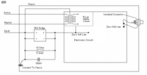
In Rob Elliot's article, (which is what this appears to be based on), he shows how to create the "loop breaker" circuit. This is illustrated with a diagram that shows the "Power Supply Circuit" on the inside of the "zero volt" area. The implication, (in the diagram), is that the complete power supply circuit, including the transformer, is connected to the zero-volt line, rather than true ground. A couple of paragraphs down, Rob points out, (in italics, no less), . . . Do not use any loop breaker circuit to isolate the transformer core, as it is unnecessary and dangerous to do so.
Unfortunately, Nuuk doesn't include this line in his article, but he still uses the diagram. To make matters worse, he suggests isolating the transformer from the chassis with rubber washers, in order to minimize mechanical vibration.
Now we have a situation where some newbie might be taking measurements inside his "live" amp, with a transformer that has in internal short to its frame. The largest chunk of metal in his circuit may have live AC on it, without blowing any fuse or tripping any breaker.
On a sidenote: IMHO, the "loop breaker" circuit shouldn't really be included in a "beginners" guide to power supply design. Its a "cute" way to resolve a ground loop problem, but its not something that I've ever seen utilized in any piece of electronic gear, consumer or pro, in forty-something years of electronics tech. I don't believe that all of this equipment is out there as a safety hazard. Just my 2-cents worth. 😉
Maybe the diagram could be editted to something like this:
Attachments
Hi Artie,
somewhat facetiously, I'm going to ask you to describe how you would connect a toroid transformer as you have shown?
somewhat facetiously, I'm going to ask you to describe how you would connect a toroid transformer as you have shown?
A lot of beginners won't be using toroids. Rob Elliot, himself, stresses the quote I have in bold above. I just think, for the sake of safety, that it be mentioned. 😎
Artie, I'm still trying to understand what you are saying (but that's a wake-up to me that something in the PSU article may need clarifying further).
When I have used a clamp-mounting type of transformer (ie with a metal frame), I have always connected the frame to mains earth. So even if I use rubber washers under it, it is still connected to mains earth, albeit using a wire rather than one of the bolts through the frame to the equipment chassis.
Come to think of it, now you bring up this subject, I would suggest that this is another reason for beginners to use a toroid transformer, although we all know that DIYers will often use what they have in the parts box if it saves them money!
This is what I don't understand! Isolate the transformer core from what? From the mains, or the circuit that it is powering?
But thanks for bringing this up. If there is something that needs correcting, or clarifying in the PSU article, then it will be once we understand what that is.
When I have used a clamp-mounting type of transformer (ie with a metal frame), I have always connected the frame to mains earth. So even if I use rubber washers under it, it is still connected to mains earth, albeit using a wire rather than one of the bolts through the frame to the equipment chassis.
Come to think of it, now you bring up this subject, I would suggest that this is another reason for beginners to use a toroid transformer, although we all know that DIYers will often use what they have in the parts box if it saves them money!
Do not use any loop breaker circuit to isolate the transformer core, as it is unnecessary and dangerous to do so.
This is what I don't understand! Isolate the transformer core from what? From the mains, or the circuit that it is powering?
But thanks for bringing this up. If there is something that needs correcting, or clarifying in the PSU article, then it will be once we understand what that is.
Good morning Nuuk. 🙂
Thats great, but you don't actually say that on your webpage article. Its important to note that the quote, you have above, is from Rob Elliot's webpage. Not me.
There's two different issues here:
1. Apparently, according to Rob, its not unheard of, for a transformer to short internally to the frame. (Although, I've never seen it happen.) I'm just afraid that a beginner might not take the time to follow the links to Rob's page, and read the whole article, and then might miss the part about not isolating the tranny frame from ground. The problem is compounded by the fact that the diagram doesn't show it.
2. The second issue is the inclusion of Rob's "loop breaker" circuit in a "beginners guide". Thats far from a universally accepted practice. (I've never seen it done, anywhere.) That doesn't make it a bad idea, but it opens a whole new can-'o-worms for the beginner. More opportunity for mistakes, if you will.
I hope I haven't blown this up into more than it is, but you stress safety in your first post. Its just something that caught my eye. Perhaps, a short sentence on grounding the tranny would suffice.
Anyway, its a great article.
Artie
Nuuk said:When I have used a clamp-mounting type of transformer (ie with a metal frame), I have always connected the frame to mains earth. So even if I use rubber washers under it, it is still connected to mains earth, albeit using a wire rather than one of the bolts through the frame to the equipment chassis.
Thats great, but you don't actually say that on your webpage article. Its important to note that the quote, you have above, is from Rob Elliot's webpage. Not me.
There's two different issues here:
1. Apparently, according to Rob, its not unheard of, for a transformer to short internally to the frame. (Although, I've never seen it happen.) I'm just afraid that a beginner might not take the time to follow the links to Rob's page, and read the whole article, and then might miss the part about not isolating the tranny frame from ground. The problem is compounded by the fact that the diagram doesn't show it.
2. The second issue is the inclusion of Rob's "loop breaker" circuit in a "beginners guide". Thats far from a universally accepted practice. (I've never seen it done, anywhere.) That doesn't make it a bad idea, but it opens a whole new can-'o-worms for the beginner. More opportunity for mistakes, if you will.
I hope I haven't blown this up into more than it is, but you stress safety in your first post. Its just something that caught my eye. Perhaps, a short sentence on grounding the tranny would suffice.
Anyway, its a great article.
Artie
Artie, I agree about grounding the metal-cased trannies and have added that warning to the article. In my own case, I have only used toroids for some years now so thanks for bringing this issue to my attention.
But I am still unsure of your other point. The diagram that you query on a previous post is Rod Elliot's. If there is a mistake with it, or you think that there is, surely he is the one to ask about it.
But I am still unsure of your other point. The diagram that you query on a previous post is Rod Elliot's. If there is a mistake with it, or you think that there is, surely he is the one to ask about it.
Again, I don't mean to belabor the point, but the reason I mentioned it to you, rather than Rob, is because he uses that diagram in an article on "grounding", in a "Tips and Tricks" section. You use it in a beginners guide to power supply design. Consequently, you don't include all of the text that Rob does leading up to that diagram. (And after.)
The two pertinent texts from Rob's site are:
and . . .
Its probably not a huge deal. I just wanted to point it out since you use Rob's (somewhat) misleading diagram.
Feel free to use the one I've modified, if it helps. (I'm not sure it does.)
Artie
The two pertinent texts from Rob's site are:
The only exception is if a double insulated mains transformer is used, but these are rare. Should the transformer be of "conventional" construction (not a toroidal), then the transformer body - the steel core - must be connected to chassis directly. Do not use any loop breaker circuit to isolate the transformer core, as it is unnecessary and dangerous to do so.
and . . .
In some cases, a transformer may be fitted with an electrostatic shield, which are lamentably uncommon in hi-fi transformers. Where provided, these too must be connected directly to the main earth point, and not via the loop breaker. Again, this is unnecessary and potentially dangerous.
Its probably not a huge deal. I just wanted to point it out since you use Rob's (somewhat) misleading diagram.
Feel free to use the one I've modified, if it helps. (I'm not sure it does.)
Artie
the reference to dangerous in both quotes is wrong.Artie said:
The two pertinent texts from Rob's site are:
Do not use any loop breaker circuit to isolate the transformer core, as it is unnecessary and dangerous to do so.
and . . .
In some cases, a transformer may be fitted with an electrostatic shield, which are lamentably uncommon in hi-fi transformers. Where provided, these too must be connected directly to the main earth point, and not via the loop breaker. Again, this is unnecessary and potentially dangerous.
The Disconnecting Network shown in ESP and Nuuk's sites can pass domestic rates of fault current to the protective earth (PE).
The one I tested showed no signs of damage to any of the components not even the low power resistor (600mW) and low voltage capacitor (50Vdc).
Parts suppliers?
I have recently started building Chip amps and found a very nice EI trafo that came out of a Parasound amp that blew up. I have been studying the various regulated schemata floating around on this forum and have decided to build a regulated PSU using this trafo. It is a 29.5-0-29.5 trafo so really I can probably use it without a regulated PSU but I want to try one. I like the design found at DOGBREATH.DE but I have one problem.....finding a parts supplier for these parts. Can anybody point me in the right direction in finding 2, 5, 10 watt wirewound resistors and the LM338? I found the LM338 at Farnell.com but there are x2 different ones with different specs...one with a 35v max input voltage and the other with 40v. ????? to use ????? Anyway, if anybody out there can help or, if anybody has a few of these parts to build one regulated PSU I would purchase them from you.
Thanks alot y'all,
Jeff Miller
Lawton, USA
millerjeff@ccmhonline.com
Your traffo is going to put out around 42 volts after the rectifier bridges!
I think that the figures you are referring to for the LM338 are for Input Output Voltage Differential, that is the difference between the input voltage and the output voltage, rather than the maximum input voltage.
So you could use your traffo for a regulated supply down to around 7 volts although you obviously don't need to go that low for a GC.
Farnell sell the wirewound resistors that you talk about . 😉
Jeff,
That transformer will give about 41 volts DC which is way too high for a chipamp. Of course you could regulate it down but that will be a lot of power turned into heat unless you use a very sophisticated switched regulation system that will probably be too expensive. Good luck
Ted
That transformer will give about 41 volts DC which is way too high for a chipamp. Of course you could regulate it down but that will be a lot of power turned into heat unless you use a very sophisticated switched regulation system that will probably be too expensive. Good luck
Ted
Hi,
your 29.5Vac transformer could charge the smoothing caps to about 46Vdc when very lightly loaded and mains is 6% high.
Don't think about using a 36 or 40V rated regulator.
your 29.5Vac transformer could charge the smoothing caps to about 46Vdc when very lightly loaded and mains is 6% high.
Don't think about using a 36 or 40V rated regulator.
29.5v trafo
I thought the maximum input voltage for the LM3886 was 42v. I have tested my trafo on the rectifier and with the diode drop it measures exactly 40v DC. Couldn't I just use this in an unregulated fashion with the LM3886? I have built one with a 38.5v DC unreg supply without problems. What's another 1.5v? Is there an easy way to shave a couple of volts off the rails, maybe a resistor in parallel and series on the leads? I remember reading somewhere, I think in the art of electronics a way to create a voltage drop by putting a resistor in parallel and series on one of the leads but I don't remember the details of this. Any thoughts?
I thought the maximum input voltage for the LM3886 was 42v. I have tested my trafo on the rectifier and with the diode drop it measures exactly 40v DC. Couldn't I just use this in an unregulated fashion with the LM3886? I have built one with a 38.5v DC unreg supply without problems. What's another 1.5v? Is there an easy way to shave a couple of volts off the rails, maybe a resistor in parallel and series on the leads? I remember reading somewhere, I think in the art of electronics a way to create a voltage drop by putting a resistor in parallel and series on one of the leads but I don't remember the details of this. Any thoughts?
Re: 29.5v trafo
First impression is that is is NOT a 29.5Vac transformer.
Feed the computers with nonsense and they spit out nonsense in return.
and what was the mains voltage when you carried out this test?jmillerdoc said:I have tested my trafo on the rectifier and with the diode drop it measures exactly 40v DC.
First impression is that is is NOT a 29.5Vac transformer.
Feed the computers with nonsense and they spit out nonsense in return.
The maximum voltages for the 3886 are 94Vdc and 84Vdc.
See absolute maximum ratings.
What is your maximum voltage from your supplier?
Write or phone and ask them directly.
Then, find out the maximum voltage that the transformer will charge the smoothing caps to, to find if you can meet both conditional maxima.
See absolute maximum ratings.
What is your maximum voltage from your supplier?
Write or phone and ask them directly.
Then, find out the maximum voltage that the transformer will charge the smoothing caps to, to find if you can meet both conditional maxima.
BrianGT power supply
I have an extra PSU from a dual mono kit that I ended up not using in a dual mono config. Brians's PSU has x4 output leads a V-, PGND-, PGND+, and V+. I tried hooking the PGND's together to get a 35v(+) - 0 - 35(-) standard 3 power lead out configuration but when I did this it obviously begins to short out. Why can't I connect his PSU up this way? I was going to use this PSU in a point to point build, now I don't know what to do.
Any suggestions?
Jeff
clarification
Sorry, I should clarify...the PSU above was one purchased from Chipamp.com....If you didn't already put that together.
Jeff
Sorry, I should clarify...the PSU above was one purchased from Chipamp.com....If you didn't already put that together.
Jeff
Coupling the two separate PSUs together should work.
The amp PCB does the same thing, joins the two PNGD lines together, to create the zero volts reference and a dual polarity supply.
Go back and check your wiring.
To build two separate PSUs from a single transformer the transformer MUST HAVE dual secondaries. One cannot build separate PSUs from a centre tapped secondary.
- Home
- Amplifiers
- Chip Amps
- Chip amp power supply- a beginners guide