Nice build CanAm Man 
I have a pair of those boards complete and working with a PSU board too, just need a new enclosure for them since their old one is now a mono block My-Ref FE 😀
Another project I might get around too, they do sound very good but the FE's are like them on steroids so they are in the big cardboard box of possibility's for now. I might put together an amp for the lad out of them when he gets out of the army, that would be nice to do.
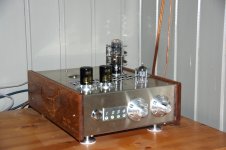
Hybrid
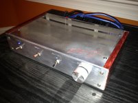
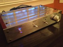
Last project done.
50W@8ohm and 72W@4Ohm (RMS @1Khz)
LM3886 + ECC83 + 5V4G
Chassis and all is made by me.
I was quit impressed with the performance on this amp, it is nothing I tried before and it plays really clear and open
For those of you that use Facebook can use this LINK to get more pictures.
Last project done.
50W@8ohm and 72W@4Ohm (RMS @1Khz)
LM3886 + ECC83 + 5V4G
Chassis and all is made by me.
I was quit impressed with the performance on this amp, it is nothing I tried before and it plays really clear and open
For those of you that use Facebook can use this LINK to get more pictures.
Attachments
OK, I'll admit to being totally confused. Can you walk us through the elements in that build. It looks very intriguing and unique, but more info would be great.🙂
Can you walk us through the elements in that build. It looks very intriguing and unique, but more info would be great.🙂What are you wondering about?
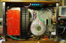
It is quit simple, LM3886 as classic Voltage amplifier working on +-37V and PSU capable of 8amps. 5V4G as tube rectifier for ECC83, working on 180V.
One PCB board for changing in signal, one PCB board for on/off with a PSU on 12V, on/off switch is based on push button and CD4013 for switching relay.
Hope this clarify some of it 🙂
Yes it does, thanks. I've done several LM3886 projects and didn't understand the integration of the tubes. What is the advantage of the "5V4G as tube rectifier for ECC83"? It's just something new to me. Always wanting and willing to learn.😉
Last edited:
5V4G is just something I had several laying in around for a long time so why not use it?
I normally build tube amps, this is just something I had to try.
I still have about 10pc of LM3886 in stock and a lot of different tubes, start a new project every winter just for fun.
I normally build tube amps, this is just something I had to try.
I still have about 10pc of LM3886 in stock and a lot of different tubes, start a new project every winter just for fun.
wcleungoo Why three fuses?
The fuse are for the +35, -35 and the MP3 12v.
ciao
wc
LME49811/Toshiba mosfets + PSU
Amplifier:
2*4W/8R Class-A
2*80W/8R Class-AB

PSU:
260VA, linear regulated quad rail +/-43V 1A, +/-36V 5A current limited

Amplifier:
2*4W/8R Class-A
2*80W/8R Class-AB
PSU:
260VA, linear regulated quad rail +/-43V 1A, +/-36V 5A current limited
Very nice.. Pics of the inside?
Sorry, no...
You have to live with this:
http://www.diyaudio.com/forums/chip-amps/79303-chip-amp-photo-gallery-259.html#post3711283
Amplifier:
2*4W/8R Class-A
2*80W/8R Class-AB
PSU:
260VA, linear regulated quad rail +/-43V 1A, +/-36V 5A current limited
Where did you get the chassis?
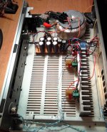
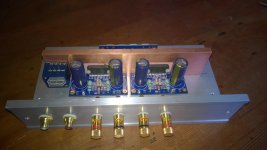
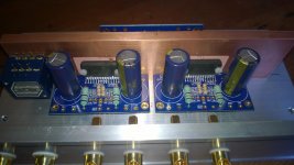
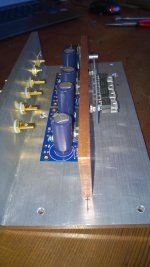
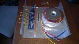
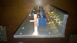
Progress build LM4780 amp
Here the progress of the build of my LM4780 parallel amp from P. Daniel
The pictures shown are of the amp upside down, the sides I want to cover with oak wood and the bottom will stay open.
The transformer is 2 x 25V 10A 500VA
The heat-sink inside is a copper bar 8 x 50 x 200mm
The cover is aluminum 7mm thick
The star ground I've planned in the middle of the copper bar
The insulation between the LM4780 and the heat-sink is made with silica pads without paste.
I've used an Alps pot for volume control.
Any comments and/or suggestions are very welcome
Greetz,
Joery
Attachments


- Home
- Amplifiers
- Chip Amps
- Chip Amp Photo Gallery