Not sure if I ever posted a photo of my finished dual LM3886 job. I originally planned for two physically separate amps, one to sit by each speaker, but later decided to put them into the same chassis which accounts for the rather space-wasting design (it's a 3U 19" rack enclosure). Anyway, I've been happy with it for a few years now 🙂

Not sure if I ever posted a photo of my finished dual LM3886 job. I originally planned for two physically separate amps, one to sit by each speaker, but later decided to put them into the same chassis which accounts for the rather space-wasting design (it's a 3U 19" rack enclosure). Anyway, I've been happy with it for a few years now 🙂
Very nice, I would only change the power switch for a push in switch and I would add a Blue/green led on front to show amp is on.
I have a thing for toggle switches 🙂 But power indicators on the front are definitely on the 'to do list', though I'll probably go for red neon bulbs rather than LEDs.
I have a thing for toggle switches 🙂 But power indicators on the front are definitely on the 'to do list', though I'll probably go for red neon bulbs rather than LEDs.
LEDs will last longer! I find blue led are very nice.
Lost Eden: One might try to find one of those lighted toggle switches:
An externally hosted image should be here but it was not working when we last tested it.


I have a thing for toggle switches 🙂 But power indicators on the front are definitely on the 'to do list', though I'll probably go for red neon bulbs rather than LEDs.
Neons can cause interference/noise.
dac/ pre/ power amp
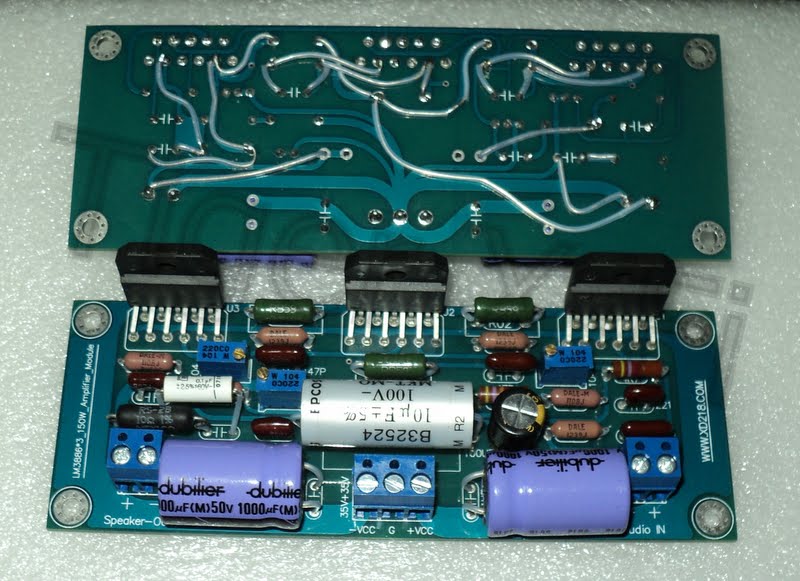
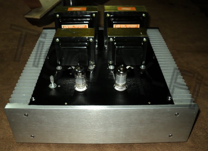
New project Unfinished,have problems with hum.
Looks good... hope you trace the problem.
Where did you get the case with the heatsink sides in the last picture from please?
"have problems with hum."
I see a lot of unshielded, barely twisted wire.. That might be a good place to start.
But it does look good..
I see a lot of unshielded, barely twisted wire.. That might be a good place to start.
But it does look good..
Maybe the DAC board is too close to that bunch of "noisy" EI transformers?
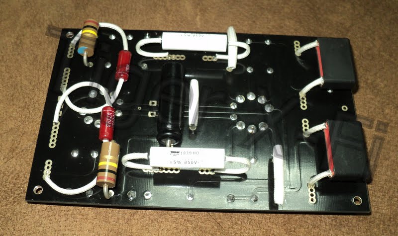
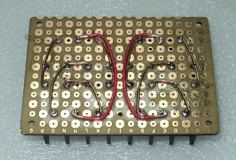
I like that way of assembling the rectifier bridge, never seem it before 🙂
I like that way of assembling the rectifier bridge, never seem it before 🙂
thunk youLooks good... hope you trace the problem.
Where did you get the case with the heatsink sides in the last picture from please?
Aluminium Chassis
I bought from web in Thailand ,maybe oder to come from China.
thunk you"have problems with hum."
I see a lot of unshielded, barely twisted wire.. That might be a good place to start.
But it does look good..
thunk youMaybe the DAC board is too close to that bunch of "noisy" EI transformers?
I like that way of assembling the rectifier bridge, never seem it before 🙂
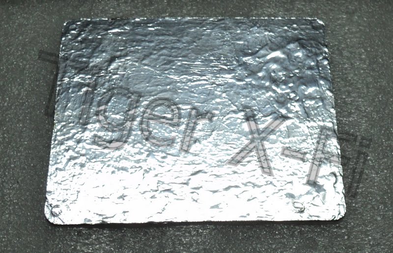
I use that (cooking foil put on pcb) under PCB DAC
(2 layer frist cooking foil put on pcb/second layer PCB DAC )
wire all= Teflon wire silver plat
I checked.
dac ok
pre have problems (12ax7&12au7)
power amp ok
maybe hum from pre tube (Heater)
I will try. use mc7806
+6 for pin 4/5
0 for pin 9
--------------
Unfortunately with bad language.
Last edited:

Diode i use 25a Because this Series in Thailand is sold only 25a
Vishay HEXFRED® Ultrafast Soft Recovery Diode, 25 A
http://www.vishay.com/docs/94064/hfa25pb6.pdf
Vishay HEXFRED®
Vishay - Diodes - Rectifiers - Ultrafast Recovery Hexfred®
Last edited:
While aliminium may be effective against EMI radiation, the MAGNETIC field from a transformer would only be shielded if using steel or any mu metal. I'm afraid aluminium or even copper should render useless for that purpose. Anyway, you still have the top aluminium cover acting as an EMI shield, so there should be no point in using that extra layer 🙂thunk you
Aluminium Chassis
I bought from web in Thailand ,maybe oder to come from China.
thunk you
thunk you
I use that (cooking foil put on pcb) under PCB DAC
(2 layer frist cooking foil put on pcb/second layer PCB DAC )
wire all= Teflon wire silver plat
I checked.
dac ok
pre have problems (12ax7&12au7)
power amp ok
maybe hum from pre tube (Heater)
I will try. use mc7806
+6 for pin 4/5
0 for pin 9
--------------
Unfortunately with bad language.
The cooling is total overkill for 100W amp...
Chips in use are LM3875 at +-30V Cap bank almost 1F...
capture screen
Chips in use are LM3875 at +-30V Cap bank almost 1F...
An externally hosted image should be here but it was not working when we last tested it.
capture screen
Last edited:
The cooling is total overkill for 100W amp...
Not neccesarily, it's allways a good idea to maintain the lowest possible die temp to keep the spike protection happy🙂
An externally hosted image should be here but it was not working when we last tested it.
An externally hosted image should be here but it was not working when we last tested it.
An externally hosted image should be here but it was not working when we last tested it.
An externally hosted image should be here but it was not working when we last tested it.
2 laptop smpsu for +-19v 2x lm3886 on amd cpu heatsink with small fan , i think it is around 20w*2 and it gets barely warm on normal listening
Here's my first electronics project, pretty much buttoned up. It's a pair of LM1875 chips built with BrianGT's kit and the standard Avel transformer. The enclosure is sort of a cobbled-together prototypical thing since I wanted it done in time for a party this weekend; I was inspired by Make magazine to build a powered speaker to use in the fabrication shop where I work, and I was going to base it on the Monobox but the more I looked at the Monobox the more I felt it was underpowered. I started looking around for alternatives and decided a Gainclone was just the ticket. Then I started to realize that the Gainclone is way overkill for a shop stereo (what with all the machine noise and forklifts and stuff), so it's probably gonna live at home with me since it's nicer than my current receiver while I figure out an even cheaper shop solution.

Here's the thing assembled. Down the line it's gonna get a custom aluminum enclosure, since it runs pretty hot and takes up more space than it needs to.

And here's the guts. It being my first project, a lot of it is pretty amateurish (the back panel isn't drilled at the right height for the LM's through-holes, meaning that the PCB base sits at a slight angle). There's a lot of solder and electrical tape where there should instead be crimped terminals and heatshrink, the LED is just floating in there, I accidentally only bought one set of speaker terminals so there's a pair of output wires temporarily sticking out the top, etc, but it works!
An idea is to build it into a water-(and beer-)resistant Al case and do the same with a pair of speakers that'll latch on for transportation, but it took about 30 hours to build this thing so it's time for a lil break from DIY projects (not a very long break, though. this was really satisfying).
I've learned a ton and gotten a lot of really good ideas from reading threads here, so thanks for that! I'll try to return the favor by posting more pics when the enclosure gets rebuilt.
Here's the thing assembled. Down the line it's gonna get a custom aluminum enclosure, since it runs pretty hot and takes up more space than it needs to.
And here's the guts. It being my first project, a lot of it is pretty amateurish (the back panel isn't drilled at the right height for the LM's through-holes, meaning that the PCB base sits at a slight angle). There's a lot of solder and electrical tape where there should instead be crimped terminals and heatshrink, the LED is just floating in there, I accidentally only bought one set of speaker terminals so there's a pair of output wires temporarily sticking out the top, etc, but it works!
An idea is to build it into a water-(and beer-)resistant Al case and do the same with a pair of speakers that'll latch on for transportation, but it took about 30 hours to build this thing so it's time for a lil break from DIY projects (not a very long break, though. this was really satisfying).
I've learned a ton and gotten a lot of really good ideas from reading threads here, so thanks for that! I'll try to return the favor by posting more pics when the enclosure gets rebuilt.
 Please remember to resize your photos before posting. No need for 1 MB images on the web. Thanks.
http://www.diyaudio.com/forums/everything-else/183084-pictures-why-not-attach-them.html
- Home
- Amplifiers
- Chip Amps
- Chip Amp Photo Gallery