
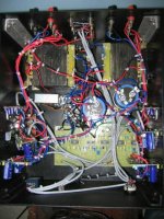
This is how it was before i blew one of the transformer....
The amp is now much better laid out than before and there are no hums or hiss noises.
There are also no heating issues.
----------------------------------------
Parts that were made redundant
Transformer for the xover was removed and extra windings were made on the new tranny.
---------------------------------
The parts that were blown were...
Transformer-1 (350VA)(replaced with a similar rated one)
Bridge rectifiers-2( replaced with International Rectifier ones)
Capacitors..6X4700uF(replaced with 2x13000uF)
One LM4780 board(mids amp module)
replaced both the mid amp modules with LM4732 amps.
----------------------------------------
The entire amp was cleaned out..stirpped off all components laid bare and re built from scratch..
The position of the crossover too was changed to place it in the center so as to allow easy access to the trimmer pots.
The height of the Xover PCB spacer was increased..the board is now 50mm from the base plate of the amp.
The layout could have been better..much better but for the fact that the mouting of the ICs did not facilitate a neater layout..
Ideally a single tranny with only one wire from the capacitors to the amp modules would have been desired(that was the idea actually).
Since i had already drilled holes for the ICs and redoing them involded too much work we elected to try to make the best of it.
I have two Lm4780s in bridged mode[lows]
Two LM4732s in bridged mode[mids]
and two LM3886s in Non inverted mode[highs].
and a single OPA541 for the center channel.
Previous amp had some oscillation problem when i played around with the gains on the xover...no such problem now .
Attachments
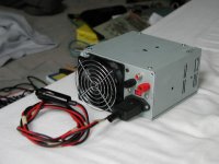
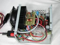
luka said:This is my car amp in ATX power supply case. Amp is LM3886
You might want to see if you can slip a piece of PCB material in between the toroid and the PCB as shielding.
All transformers radiate -- in the case of switching supplies the radiation is very pronounced and will seriously affect the performance of the amplifier -- any amplifier.
So you have a trade-off between shielding the space between the amp PCB and power supply on one hand, and switching noise, unpredictable offset voltage etc. on the other.
See Linear Technologies Application Note 70.
So you have a trade-off between shielding the space between the amp PCB and power supply on one hand, and switching noise, unpredictable offset voltage etc. on the other.
See Linear Technologies Application Note 70.
No, not really --
If you can access an oscilloscope take a look at the output waveform with and without a piece of shielding -- on the Hafler DH200/220 mods thread I pointed out that inserting shielding between the transformer and the low-level circuit boards cut THD by an 0.001% -- in the case of the Hafler 220 which I was working on I tried to reduce the transformer radiation -- remember we are working with a 60 Hz rectified sine wave so the level of problems are much lower than the square wave from a switcher.
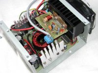
I am making a leap of judgement here, assuming that you are using an SG3525 switching regulator.
If you can access an oscilloscope take a look at the output waveform with and without a piece of shielding -- on the Hafler DH200/220 mods thread I pointed out that inserting shielding between the transformer and the low-level circuit boards cut THD by an 0.001% -- in the case of the Hafler 220 which I was working on I tried to reduce the transformer radiation -- remember we are working with a 60 Hz rectified sine wave so the level of problems are much lower than the square wave from a switcher.
I am making a leap of judgement here, assuming that you are using an SG3525 switching regulator.
yes I am using 3525 in car,
Ok I'll look output with scope again.
I am not happy with the spikes on output, but I dont tkink I can hear any of them. they are some 0.5vp high or so.
Ok I'll look output with scope again.
I am not happy with the spikes on output, but I dont tkink I can hear any of them. they are some 0.5vp high or so.
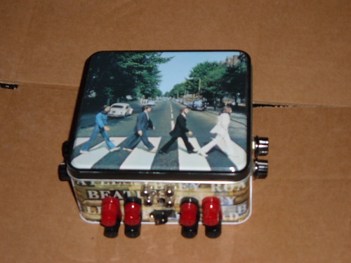
The Beatles Tin Amp
My, "BEATLE TIN AMP"
A Four channel stereo bi-amp run from a 30V battery source'
My, "BEATLE TIN AMP"
A Four channel stereo bi-amp run from a 30V battery source'
The Beatles Tin Amp
My, "BEATLE TIN AMP"
A Four channel stereo bi-amp run from a 30V battery source.
Passive crossover at 500hz, Each pot controls a different channel.
Has Zobels, " the big resisters"
Modified many times.
This Beatle Amp is a Dead Bug Amp! , Get It?
Pun
The Inside
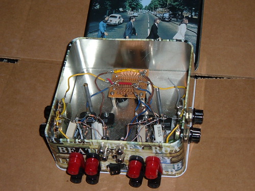
My, "BEATLE TIN AMP"
A Four channel stereo bi-amp run from a 30V battery source.
Passive crossover at 500hz, Each pot controls a different channel.
Has Zobels, " the big resisters"
Modified many times.
This Beatle Amp is a Dead Bug Amp! , Get It?
Pun
The Inside
My own "Gainclone":
http://www.darkmatter.myby.co.uk/projects/50w-amp/images/all.JPG
I bought the case on eBay which had some type of power supply (500VA toroid!) and control processor in it. Unfortunately the toroid wasn't suitable. The back panel is nasty thin metal that I happened to have lying around, I plan to replace this soon with a piece of the same 1.5MM metal that makes up the front panel.
As you can see, there is a set of 4 input jacks on the back. I plan to add a preamp and input select circuit to this soon. The transformer is some unit I had lying around that puts out 25-18-0-18-25. It is under rated but is OK for the low volumes that the amplifier is currently used for. I will be replacing it with a 225VA 18-0-18 transformer soon.
The capacitors are 4x4700uF 63V BHC Aerovox capacitors that I aquired cheap on eBay.
DAB i hope thats not the beatle tin thats worth $2000 on ebay 🙂
anyways its very cool, nice job!
anyways its very cool, nice job!
LEDS
John,
Have you thought about getting professional help with this obsession you have with blue LED's?
😉
They look good mate.
Brett
John,
Have you thought about getting professional help with this obsession you have with blue LED's?
😉
They look good mate.
Brett
Re: LEDS
I likeee them like that! Now that i'm started down the path everything has to match, and one problem is that I have a bag of 100 to use up. But note that the last amp only has 1 blue led in the whole thing, so i'm getting better. Plus the preamp is causing me to go blind.
enzedone said:John,
Have you thought about getting professional help with this obsession you have with blue LED's?
😉
They look good mate.
Brett
I likeee them like that! Now that i'm started down the path everything has to match, and one problem is that I have a bag of 100 to use up. But note that the last amp only has 1 blue led in the whole thing, so i'm getting better. Plus the preamp is causing me to go blind.
- Home
- Amplifiers
- Chip Amps
- Chip Amp Photo Gallery