Thanks for your interest. The project is still a ways off as I'm still in the conceptual design stage, and the various hardware modules it will need to include. Not to mention the software it will require. I will solicit my son's help for that! 🙂Hi redjr,
This project is very interesting for me since I was looking for such a device for a long time. For the time being I am using a Chinese media player as a source but quality is not satisfying. Unfortunately I am not an expert in the field and can hardly manage to build it myself but can try to follow your project if you share the experience.
Otherwise I have a standalone heavy modded DAC based on TDA 1541 A, tube preamp and three power amps driving six speakers.
Please comment,
Thanks
Rick
Niamex, I have two Pi servers currently in use. A Pi2B with HiFiBerry + DAC running Volumio 2 and my main unit a Pi3B with external highend DAC board running Rune 0.4.
I'm extremely pleased with the versatility and audio results. With no screen, keyboard or mouse I have a Pi server running from scratch in 15mins. It is crazy simple once you know how and all software is free and there is no hacking. I just use the config. menus in Rune or Volumio. A Pi2B is really all you need but the 3 has built in wifi and blue tooth.
I'm extremely pleased with the versatility and audio results. With no screen, keyboard or mouse I have a Pi server running from scratch in 15mins. It is crazy simple once you know how and all software is free and there is no hacking. I just use the config. menus in Rune or Volumio. A Pi2B is really all you need but the 3 has built in wifi and blue tooth.
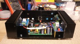
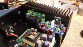
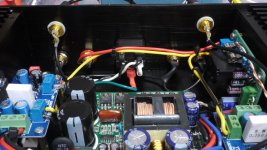
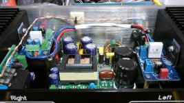
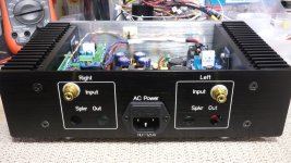
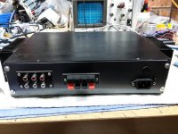
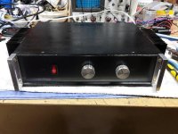
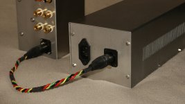
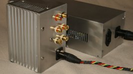
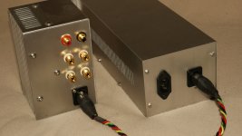
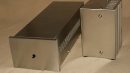
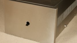
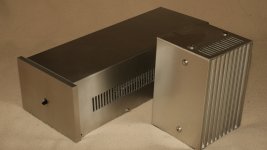
Most Recent Build - Mini 3886
Here are some pics of my most recent chipamp build. I'm calling it the Mini 3886.
Rick
Here are some pics of my most recent chipamp build. I'm calling it the Mini 3886.
Rick
Attachments


Niamex, I have two Pi servers currently in use. A Pi2B with HiFiBerry + DAC running Volumio 2 and my main unit a Pi3B with external highend DAC board running Rune 0.4.
Hi, thanks your comment.
I have at hand one brand new old model - do not know whether suits - E2212RSV1.08 1.1. Please advise what else I need to buy in order to follow the project. The idea is to watch and listen to my concerts and manage the content of my SD cards /or hard discs/ by remote using the TV /hdmi/ for reaching the files and playing through DAC.
Thanks in advance,
Ignat
I have only been working with Pis for a few weeks so hard for me to say.
I have only been working with Pis for a few weeks so hard for me to say.
I think it is PI ?
Attachments

I haven't seen that one. Digital out?
It looks like a Raspberry Pi ver 1. Go to the raspberry pi site for spec details and info re pins.
Here are some pics of my most recent chipamp build. I'm calling it the Mini 3886.
Rick
how is the switching PSU doing in this amplifier? no problems with high frequency noise?
I've had no 'audible' issues with using an SMPS. Most of my chipamps use an SMPS, except for the PA03, LM4780 I built last year. The PCB already had an on-board rectifier and filter caps, so I went with a linear in that case.how is the switching PSU doing in this amplifier? no problems with high frequency noise?
I find SMPSs much smaller, efficient and easily work well with these smaller amps. Especially, if you want to design something with an overall smaller footprint.
Rick
Nice build 🙂
Sure those are easy to work with and cost effective too. But regarding size you are still wasting space, you don't need that much heat sink for 2x LM3886. Putting them side by side also minimizes common ground issues with a single PSU. I guess my 2x mono build is about the same size (320 x 70 mm's): http://www.diyaudio.com/forums/chip-amps/79303-chip-amp-photo-gallery-75.html#post4663745
I find SMPSs much smaller, efficient and easily work well with these smaller amps. Especially, if you want to design something with an overall smaller footprint.
Rick
Sure those are easy to work with and cost effective too. But regarding size you are still wasting space, you don't need that much heat sink for 2x LM3886. Putting them side by side also minimizes common ground issues with a single PSU. I guess my 2x mono build is about the same size (320 x 70 mm's): http://www.diyaudio.com/forums/chip-amps/79303-chip-amp-photo-gallery-75.html#post4663745
Last edited:
Yeah, I know the heat sinks were overkill, but the only small case I had on hand. 🙂 They'll never get hot, much less warm!Nice build 🙂
Sure those are easy to work with and cost effective too. But regarding size you are still wasting space, you don't need that much heat sink for 2x LM3886. Putting them side by side also minimizes common ground issues with a single PSU. I guess my 2x mono build is about the same size (320 x 70 mm's): http://www.diyaudio.com/forums/chip-amps/79303-chip-amp-photo-gallery-75.html#post4663745
Boosted LM1875 Amplifier
I have used an old kit from Jaycar/Dick Smith electronics called "The Schoolies Amplifier" (some DIYers in Australia will know this kit) which was very popular as a novice project for schools to build a DIY amplifier. I had some PCB'S lying around and saw it was very easy to modify and implement booster transistor outputs to improve the output especially at 4 ohms. This amplifier works a treat!. You still have all the great benefits of the LM1875 with gain, thermal protection etc. I am running this amp at +/- 29 volts which is the upper most limit of the chip. Into 8 ohms there is not much difference. I get 46 volts peak to peak which equates to around 33 watts RMS and at 4 ohms it is boosted to over 40 watts RMS (depending on power supply this can be more) Stand alone this chip fries at 4 ohms. It is not recommended to drive 4 ohm loads at that voltage level. But with the booster transistors most of the load is carried by the output transistors. Distortion figures are improved marginally and measure at about 0.015%.
I have used an old kit from Jaycar/Dick Smith electronics called "The Schoolies Amplifier" (some DIYers in Australia will know this kit) which was very popular as a novice project for schools to build a DIY amplifier. I had some PCB'S lying around and saw it was very easy to modify and implement booster transistor outputs to improve the output especially at 4 ohms. This amplifier works a treat!. You still have all the great benefits of the LM1875 with gain, thermal protection etc. I am running this amp at +/- 29 volts which is the upper most limit of the chip. Into 8 ohms there is not much difference. I get 46 volts peak to peak which equates to around 33 watts RMS and at 4 ohms it is boosted to over 40 watts RMS (depending on power supply this can be more) Stand alone this chip fries at 4 ohms. It is not recommended to drive 4 ohm loads at that voltage level. But with the booster transistors most of the load is carried by the output transistors. Distortion figures are improved marginally and measure at about 0.015%.
Attachments

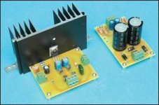
I have used an old kit from Jaycar/Dick Smith electronics called "The Schoolies Amplifier" (some DIYers in Australia will know this kit) which was very popular as a novice project for schools to build a DIY amplifier. I had some PCB'S lying around and saw it was very easy to modify and implement booster transistor outputs to improve the output especially at 4 ohms. This amplifier works a treat!. You still have all the great benefits of the LM1875 with gain, thermal protection etc. I am running this amp at +/- 29 volts which is the upper most limit of the chip. Into 8 ohms there is not much difference. I get 46 volts peak to peak which equates to around 33 watts RMS and at 4 ohms it is boosted to over 40 watts RMS (depending on power supply this can be more) Stand alone this chip fries at 4 ohms. It is not recommended to drive 4 ohm loads at that voltage level. But with the booster transistors most of the load is carried by the output transistors. Distortion figures are improved marginally and measure at about 0.015%.
Q1 = 2SC5200What are the power transistors?
Q2 = 2SA1943
Smart,
thanks for the link. Pity Billbo did not show that.
Q1 = 2SC5200
Q2 = 2SA1943
Smart,
thanks for the link. Pity Billbo did not show that.
Thanks to Google!
One must read the comments section below. It seems there are some mistakes in the PCB layout. But I am not sure.

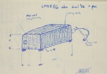
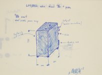
DUAL '86 stereo amplifier
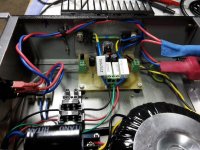
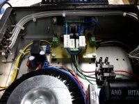
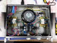
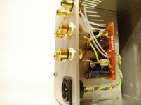
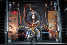
A while ago I finished my LM3886 amplifier. Power supply is in separate casing and it is made out of two Meanwell LRS-150-24 SMPS. On the PSUs outputs there are also two Panasonic FC 3300uF 35V capacitors bypassed with 100nF MKP1837. LM3886 PCB is my own design and you can find out more here: http://www.diyaudio.com/forums/chip-amps/267709-lm3886-smd-components-10.html. I have no hum or noise coming out from speakers and I am very pleased with the sound.
BR,
Aleš
p.s. M3 nuts on PSU will be replaced with decorative ones.
Attachments
-
 IMG_20150729_210657.jpg668.8 KB · Views: 620
 -
 DSC00019.JPG476.5 KB · Views: 470
 -
 DSC00017.JPG506.7 KB · Views: 512
 -
 DSC00013.JPG473.6 KB · Views: 452
 -
 DSC00012.JPG414.4 KB · Views: 359
 -
 DSC00009.JPG396.7 KB · Views: 459
 -
 DSC00006.JPG422.3 KB · Views: 473
 -
 DSC00030.JPG862.5 KB · Views: 353
 -
 DSC00032.JPG802.6 KB · Views: 693
- Home
- Amplifiers
- Chip Amps
- Chip Amp Photo Gallery