Similar listening test
https://www.diyaudio.com/community/threads/loudspeaker-for-current-drive.403936/post-7469405
https://www.diyaudio.com/community/threads/loudspeaker-for-current-drive.403936/post-7469405

试试这个完美的!不允许修改!
另外要加50赫兹高Q值高通滤波器,否则超低音不够!
Try this perfect! Modifications are not allowed!
In addition, a 50 Hz high-Q high-pass filter should be added, otherwise the subwoofer is not enough!
Please post in English as per the forum rules you have agrees to in registration with the site.
Thanks 🙂
Ok, i'll jump in with my very limited understanding ...
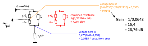
I first simulated the circuit and then tried to calculate it on paper. The electrolytic cap only affects very low frequencies and can be omitted for simplicity.
Then i made a calculation of the resistor-network to calculate the voltage resulting at the negative (feedback) amp input.
my result for voltage divider is 0.0648, resulting in a gain of 15.4 or 23,76 dB.
The loudspeaker will only see a reduced part of this gain, rest will heaten up the 0.47 ohm resistor.
Of course gain is heavily dependent on loudspeaker impedance. E.g. 4 ohm speaker would result in 18,86 dB gain (thus potentially unstable).
Attachments
But that gain only applies where the DC component of the impedance is 4 ohms, say around 200 Hz or so. For a 40 Ohm peak at 50Hz gain would be substantially higher: approx 38.86 dB, assuming the DC component is indeed 40 Ohms then. Or am I missing something here?E.g. 4 ohm speaker would result in 18,86 dB gain (thus potentially unstable).
The calculation only considers AC and assumes a pure resistive "speaker"-load.the DC component
For DC the cap should be included in the calculation and will reduce gain to unity.
But you are right, of course, like all current-drive amps gain will increase significantly as impedance rises.
Worth noting that this circuit does not provide pure current drive.
Last edited:
The TDA 2003 amp which seems not to be available any more from post
https://www.diyaudio.com/community/...fication-to-current-drive.389985/post-7199123
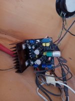
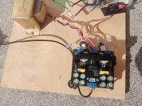
Profited from 680 microfarad now added directly on pins 3 and 5 for power supply decoupling. It's in current drive mode working.
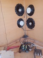
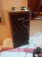
It's in use on my open baffle system:
https://www.diyaudio.com/community/threads/corner-horn-meets-open-baffle-cfa.398842/

https://www.diyaudio.com/community/...fication-to-current-drive.389985/post-7199123
Profited from 680 microfarad now added directly on pins 3 and 5 for power supply decoupling. It's in current drive mode working.
It's in use on my open baffle system:
https://www.diyaudio.com/community/threads/corner-horn-meets-open-baffle-cfa.398842/
Attachments
Subjective comparison with more modern D amp chips like tpa3116 or the like cs8673
https://www.diyaudio.com/community/threads/unboxing-zk-mt21-tpa3116.403857/post-7501910
https://www.diyaudio.com/community/threads/unboxing-zk-mt21-tpa3116.403857/post-7501910
There are always ways. But honestly, I wouldn't bother with a junk chip like that, IMHO.Does the la4282 is suitable for a modification to basic current feedback?
Any worthwhile benefit from current drive or high(er) source impedance requires a minimum fidelity from both the speaker drivers and the amplifier. The LA4282 does not qualify, I'd say.

@KSTR
If you know how to do with this one, please show me.
I can get a small amp with this chip and I would like to change it to current drive.
The TDA2003 is also considered as mediocre. But the magic is that cheap drivers without Faraday copper ring on the pole plate profit a lot from current drive mode. More than low distortion high end drivers.
The impedance of the speaker is so much lower than the internal feedback that it can effectively override it. Connect the output and - input as you would a TDA2003, capacitively coupled, with the usual value of current sense resistor. This should allow the internal DC feedback to operate normally.
I wouldn’t hold my breath as to sound quality, but it will work.
I wouldn’t hold my breath as to sound quality, but it will work.
Most of those car radio IC’s are awful. The only ones that are worse are the ones intended for cheap “all in one” 8 track/phono/AM/FM plug in stereos.
TDA2003 and it’s derivatives, and the old Toshiba TA7205 are the only ones that are even any good, IMO.
TDA2003 and it’s derivatives, and the old Toshiba TA7205 are the only ones that are even any good, IMO.
I got two amps with tpa3116 inside and see how good they sound and they put lots of watts out.
If you have loudspeakers with Faraday copper ring on the pole plate and take something between 0.15 and 0.47 ohms in series you get sound with enough absence of distortion I now tested that (by ear).
However Chip amps modified to basic current feedback are of high value if you use normal drivers
So that's my quintessence:
https://www.diyaudio.com/community/threads/unboxing-zk-mt21-tpa3116.403857/post-7501910
I answered this to you PMDoes the la4282 is suitable for a modification to basic current feedback?
View attachment 1234925View attachment 1234926
If used as a Stereo Amplifier>>>>
Well, it already has an internal built-in voltage NFB net which you can't touch: 30k - 300 ohm so it won't be pure current feedback, but you can turn it into high-ish impedance mixed feedback, quite close. Ground each speaker through a 0.22 ohm resistor and return respective NFB input to that joint using a 100uF capacitor
In theory a bipolar one: in practice a regular polarized one will do, almost zero volts dropped across it.
<<<<<
Now if you want to turn bridged amp into a current source one, forget it, solution is not impossible but complicated.
As of the "car chipamp" label mentioned before, this amp is one notch above, being powered by a 30V class supply.
Upgrade that to "TV/cheap Stereo chipamp" and we are talking 😉
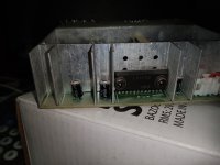
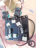
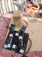
Finished and will test the Lm1875 board to current drive from post
https://www.diyaudio.com/community/...fication-to-current-drive.389985/post-7465903

Added 100 picofarad parallel at the input like described in the data sheet.
Added 680 uF decoupling for the chips.
Added 0.1uF mkt foil to the input electrolytic in parallel.
https://www.diyaudio.com/community/...fication-to-current-drive.389985/post-7465903
Added 100 picofarad parallel at the input like described in the data sheet.
Added 680 uF decoupling for the chips.
Added 0.1uF mkt foil to the input electrolytic in parallel.
Attachments

- Home
- Amplifiers
- Chip Amps
- Chip amp modification to current drive