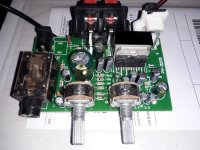
Tested now chip amp with TDA2004. From post 199 in this thread.
The current sensing resistor must be one ohm. I tested 0.5 and 0.15 ohms, too.
One ohm is just right.
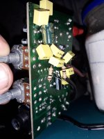
I added 1mfd MKT to all relevant electrolytics. It helps the sound.
Minimal configuration works fine with the current sensing resistor to 1 ohm (original on the pcb is 33 ohms - far too much).
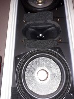
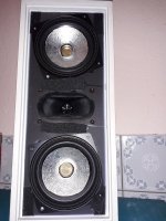
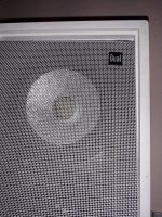
With the bass light loudspeakers I have (two 12cm fullranges with piezo tweeter in old DUAL enclosures and low tuned reflex ports close to back wall) this amplifier sings, sings, sings.
I am impressed again what current feedback does sonically to fullrange drivers.
It corrects the highs and bass "automatically" and the depth in sound gets soooo good.
Listening to radio stations reveals everything - voices sound correct, music has impact and correctness.
I am so happy with the TDA2003 / 2004!!
The current sensing resistor must be one ohm. I tested 0.5 and 0.15 ohms, too.
One ohm is just right.
I added 1mfd MKT to all relevant electrolytics. It helps the sound.
Minimal configuration works fine with the current sensing resistor to 1 ohm (original on the pcb is 33 ohms - far too much).
With the bass light loudspeakers I have (two 12cm fullranges with piezo tweeter in old DUAL enclosures and low tuned reflex ports close to back wall) this amplifier sings, sings, sings.
I am impressed again what current feedback does sonically to fullrange drivers.
It corrects the highs and bass "automatically" and the depth in sound gets soooo good.
Listening to radio stations reveals everything - voices sound correct, music has impact and correctness.
I am so happy with the TDA2003 / 2004!!
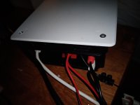
Attachments
-
 20230611_220311.jpg477.2 KB · Views: 145
 -
 20230611_220252.jpg498.2 KB · Views: 143
 -
 20230611_215802.jpg342.7 KB · Views: 128
 -
 20230611_215815.jpg757.7 KB · Views: 140
 -
 20230611_215834.jpg592.7 KB · Views: 142
 -
 20230611_215848.jpg485.9 KB · Views: 125
 -
 20230611_215858.jpg856.1 KB · Views: 131
 -
 20230611_215752.jpg305.4 KB · Views: 132

With one ohm you have an input sensitivity of one amp per volt. For a medium power amplifier and a source with plenty of voltage swing you will be able to get the full output of the amp depending on the driver impedance. On my builds I found 0.5 ohms was needed to get the full power from my amp and preamp combo, sensitivity being 2 amps/volt.
For me one ohm is just right. Maybe I can change another resistor to adjust amplification.
For the first it sounds as it should be.
With 0.5 or 0,15 ohm the box is bass shy like with voltage amplifier.
I will ad a preamp to get the loudness I need. I like the whuzi audio bluetooth 5.0 preamp for 5 euro. Its clean and has bass treble adjustment.
For the first it sounds as it should be.
With 0.5 or 0,15 ohm the box is bass shy like with voltage amplifier.
I will ad a preamp to get the loudness I need. I like the whuzi audio bluetooth 5.0 preamp for 5 euro. Its clean and has bass treble adjustment.
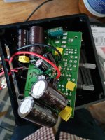
Output cap is original 10volt 820mfd. I doubled that. Not tested if its necessary.
Added to the 100mfd 16volts (feedback cap) a second one. Not tested if necessary. But the foils help the sound, they are on:
Coupling capacitors input+output. Feedback caps and for the power lines on the chip.
Added to the 100mfd 16volts (feedback cap) a second one. Not tested if necessary. But the foils help the sound, they are on:
Coupling capacitors input+output. Feedback caps and for the power lines on the chip.

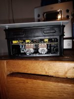
The right trim (50k) is for loudness.
The left one I guess for the microfone input. Turning it exerts some irrelevant change to the sound. Its no bass or treble knob
The left one I guess for the microfone input. Turning it exerts some irrelevant change to the sound. Its no bass or treble knob
I tested now some tweaks.
Original output cap is 10v 820mfd. Here I add at least 1000mfd or change for one with 2200mfd.
Feedback cap is 100mfd. It's too small cutting the bass. With 200mfd it sounds good. 470mfd did not do well. Here an extra 1mfd MKT foil was not of sonical profit. I just use electrolytic here. The highs sound more realistic.
The power cap is 35v 1000mfd original and it sounds nice with bass shy boxes. If you have enough bass capacitance can be popped up and it sounds then more dry and controlled. You can adjust to your taste.
All this shows that with Diy you can control the sound you wish to have perfectly.
Impossible to be content by just changing solid state amps one after another because you cannot control the design of the amp by yourself.
Tweaking by yourself it's worth the work as you learn how to change and use an amplifier matching your personal taste.
Impossible to be content by just changing solid state amps one after another because you cannot control the design of the amp by yourself.
Tweaking by yourself it's worth the work as you learn how to change and use an amplifier matching your personal taste.
Last edited:
Post distorion and spectrum for different cap values vs percieved sound. Otherwise its all just speculation.
In case you make an SPL (including a nearfield) measurement, you would quickly see you basically have created the same as a "loudness" circuit with some 6-12 dB bass lift around resonance. No magic at all.
I agree @adason and @Boden
Without measurements you do not know what is exactly going on.
I just match the small amplifier "to taste" to a special loudspeaker I built.
Often less distortion sounds less intreaguing and therefore people build diy amplifiers with some grade of distortion they like and can control.
The small TDA2004 amp is here a nice compromise: current drive helps correcting the frequency response of the box bringing distortion down and make it sound more detailed without doing all that with a classical crossover network.
On the other side the cost effective product has some compromises generating distortion which can be part of a "sound design".
Unhappy end users only buying ready made products change often their system buying and selling boxes, amps, cables and so on until they reach a sound they can live with.
For me its an experience how the sound changes while doing some "cap rolling".
TDA2004 amp:
I tried out now bipolar electrolytic 2x2200mfd 16v - combining polar Cs - for the output and bipolar for the feedback capacitor (2x 470mfd, 16v).
Reduction in distortion is clearly audible. Maybe you can get the same result by using electrolytics with higher voltage like 25/35/50v.
So for a sound design you can choose between less distortion and more distortion - just to match your taste.
I tried out now 2200mfd bipolar caps on the output. They are rated 10volts. It shows low distortion.
So what causes audible distortion is not using bipolar type (made from combined 4700mfd x 2) on the output.
Its not the low voltage of 10volts what causes the distortion. In the datasheet it's written that the output does not exceed 7v even with 18v in the power supply for the TDA2003
So what causes audible distortion is not using bipolar type (made from combined 4700mfd x 2) on the output.
Its not the low voltage of 10volts what causes the distortion. In the datasheet it's written that the output does not exceed 7v even with 18v in the power supply for the TDA2003
Attachments

Does anyone know if the bootstrap electrolytic on a chip amp like TDA2004/5 has an influence on the sound concerning its quality?
Can it make a difference if it is bipolar or even being parallel with a foil C?
Can it make a difference if it is bipolar or even being parallel with a foil C?
TDA2004 amp: Tried out 3000mfd instead of original 1000mfd power supply cap on the board.
Distortion goes up and it sounds bad.
Might be that 2000 mfd goes in the same direction and should be omitted.
Amp working with smps 2ampere 15 volts.
Putting 1mfd foil directly on + and - on the chip and putting 1mfd foil cap on the bootstrap electrolytic (100mfd) made the highs sound better.
Distortion goes up and it sounds bad.
Might be that 2000 mfd goes in the same direction and should be omitted.
Amp working with smps 2ampere 15 volts.
Putting 1mfd foil directly on + and - on the chip and putting 1mfd foil cap on the bootstrap electrolytic (100mfd) made the highs sound better.
Amplifier has least distortion with 1000mfd orginal capacitor in place. Depending on your wall wart smps you use more capacitance (2000 or 3000 mfd) sounds worse. Easily identifiable by distortion: more distortion means psychoacoustically less bass and highs.
Now this capacitance can be used to attenuate your loudspeaker although it should not be used for this. A speaker dominated by bass and highs will sound nicer with 2000 or 3000mfd with the wall wart smps mentioned (2A 15Volts). The difference in sound is prominent and therefore easy to detect.
If you really want to optimize your amplifier by ear you end up always to change only one single part and listen to it. Or you use measurements to check.
So this small TDA2004 amp sounds best:
bipolar electrolytic for feedback capacitor (+100mfd for the original 100mfd installed)
bipolar electrolytic for output capacitance
some foil capacitors on all electrolytics and directly on the plus and minus power supply pins of the chip
All in all a nice experience to make a ready made amplifier work well.
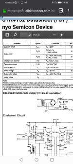
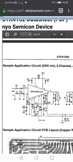
I want to order a transfomer for the stk 4132 amplifier. In the data sheet they mention a RP25 trafo - what does it mean?
Is a 15-0-15 transformer appropriate or can I take a one with more volts?
C5 is on my amp rated at 25 volts.
Is a 15-0-15 transformer appropriate or can I take a one with more volts?
C5 is on my amp rated at 25 volts.
Attachments
It's the amp from post 174
https://www.diyaudio.com/community/...fication-to-current-drive.389985/post-7274732
https://www.diyaudio.com/community/...fication-to-current-drive.389985/post-7274732
STK4132 can have max +/-34.5 VDC.
In datasheet they use +/-28 VDC for 8 Ohm load.
They use +/-20 VDC for 4 Ohm load.
I think you should use the 15-0-15 transformer. Will give like +/-21 VDC.
There is no good idea to hunt for much power. 20 Watt is more than you can use.
You can not turn up your potentiometer that high ...
25V for C5 is not critical, especially if you use +/-21 VDC
Last edited:
- Home
- Amplifiers
- Chip Amps
- Chip amp modification to current drive