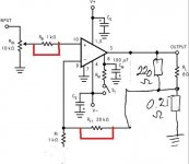
The bottom side of Ri is open rather than grounded in adason's schematic, so you don't get excessive gain.
I removed the 20uF cap, making 1k irrelevant. You can remove it or leave it hanging, both the same. And there is no dc issue.
Last edited:
Hello,
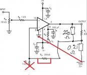
as i am not into electronics but want to understand well is the the schematic now proposed? (See attachment)
Just tell me where to attach the 0,25 Ohms to ground in the amplifier? To GND at the LM3886 chip in the shortest way?
So this schematic is for 33x amplification.
as i am not into electronics but want to understand well is the the schematic now proposed? (See attachment)
Just tell me where to attach the 0,25 Ohms to ground in the amplifier? To GND at the LM3886 chip in the shortest way?
So this schematic is for 33x amplification.
Attachments
Which one is the 20 mf electrolytic in the schematic I cannot find it?
Ah, ok found it on the original scheme from Texas Instruments. O.k.
Ah, ok found it on the original scheme from Texas Instruments. O.k.
ok, I seem to understand by taking out 22 mfd the 1k resistor to ground from pin 9 from the LM3886 plays no role any more. So my schematic is wrong as the iK of the input has to rest at its place.
There is only one ground. The ground.
Its the power supply ground. Thats where you connect signal ground, decoupling caps ground, speak out ground, Cs and Cm ground...
Read Joe Rasmussen's thread.
Or do not build current drive amp.
Its the power supply ground. Thats where you connect signal ground, decoupling caps ground, speak out ground, Cs and Cm ground...
Read Joe Rasmussen's thread.
Or do not build current drive amp.
o.k. thank you, I understand. Only pity seems to be its hard to get LM3886 chips at a reasonable price at the moment.
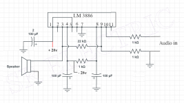
As I maybe want to hard wire this amplifier I found a schematic for doing this on this website:
https://srelectrics.com/2021/02/03/how-to-make-high-bass-100-watt-audio-amplifier-circuit/
Current drive would look like this. If there is a fault please tell here.
Attached Files: Original schematic for voltage drive, modified schematic for current drive.
https://srelectrics.com/2021/02/03/how-to-make-high-bass-100-watt-audio-amplifier-circuit/
Current drive would look like this. If there is a fault please tell here.
Attached Files: Original schematic for voltage drive, modified schematic for current drive.
Attachments
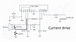
What is the intention of the 220 Ohm resistor between plus and minus at the loudspeaker output?* I didn´t even mention the 220 ohm resistor since it´sway higher than any impedance an 8 ohm speaker can take, so we can safely ignore it and simplify Math.
Is it necessary for stability or current drive operation? Or could it be left out?
Leave out that resistor. Disconnect the speaker. The amplifier has no NFB, wants to run "infinite" gain, goes out of control.What is the intention of the 220 Ohm resistor between plus and minus at the loudspeaker output?
Well-behaved amps will just go to the rail and stay there. Many amps and layouts will squeal, perhaps supersonic.
I'm not sure 220r is the 'ideal' value, I'll leave that for fans of underdamped speakers. We do see it a lot in guitar amplifiers as a fair approximation of zero-feedback power pentodes.

This worked for Peavey. The multiple feedback loops give the designer more things to tweak. Yes, it is "drawn backward" with a funny style and is single-supply and a different chip.

Hello, interesting to see this one. Could be used with simple Laptop power supply. Could be tried, too.This worked for Peavey. The multiple feedback loops give the designer more things to tweak. Yes, it is "drawn backward" with a funny style and is single-supply and a different chip.
However I think +28 is the main power supply positive rail. What is +14 Volt in this schematic for?
Should'nt C22 (1000 mfd 35 Volts) be of a bipolar type?
I use that 220 ohm just as precaution if there is no speaker connected. If there is no load, current drive amp will raise the voltage to produce current, but nothing will flow. Than someone will plug the speaker and get surprise.
If you are sure you will not mistreat the amp, you can omit it. I would not.
Good luck. You will need it.
If you are sure you will not mistreat the amp, you can omit it. I would not.
Good luck. You will need it.
Hello Adason, so nice to learn about it! I would not omit it just wanted to know what it does.I use that 220 ohm just as precaution if there is no speaker connected. If there is no load, current drive amp will raise the voltage to produce current, but nothing will flow. Than someone will plug the speaker and get surprise.
If you are sure you will not mistreat the amp, you can omit it. I would not.
Good luck. You will need it.
I will certainly try out with LM3886 as soon as I get my hands on some chips and find the time to bring it all together. It certainly has less distortion than the TDA2040.
Wish you good luck, enough to get a working chip there.
I mentioned before, and being realistic, not so deeply interested on who made the chip, as in:
so not really against "second source" or it being a "copy" or even "being different inside" as in it being usable, meeting above basic specs.
I mentioned before, and being realistic, not so deeply interested on who made the chip, as in:
- does it work?
- does it (reasonably) meet specs?
- will it survive regular use?
so not really against "second source" or it being a "copy" or even "being different inside" as in it being usable, meeting above basic specs.
D
Deleted member 375592
my 2c: all you need is to ensure 3886 stability if you use DSP to EQ. I'd use 0.22 | 0.25 Ohm in series with spk; instead of a single 220 Ohm: {4.7 Ohm + 10uF} || {4.7 Ohm + 330nF} bypassing "4Ohm" spk. Double R / half C for 8 Ohm. The gain will be ~20dB, Ft~200kHz. Basically, you need to repeat gain/tau from figure 3 in the datasheet.
D
Deleted member 375592
Functionally, I'd think you need 26dB gain on audio frequencies and a drop to 20dB from 140kHz to 280kHz (for the sake of safe phase margin). That means in line with the speaker = Re / 20. Spk impedance grows as sqrt(f), so you need to limit it. So ... something like that.

- Home
- Amplifiers
- Chip Amps
- Chip amp modification to current drive