The threads are long I know, but you can find information about the different types of inductors and their distortion measurements on these ampboards too. The xal type is high distortion if I remember correctly. For 8 ohm speakers I would consider the added components I mentioned a little earlier or a 22uH inductor.
irribeo is right, the XAL series isn't that good for Class-D filters due to soft saturation and increased THD.
Thanks for the info irribeo and Doc, it went back through the thread again and found it on page 196. So the Codaca CSCF2014-6R8M or Wurth 7443630700 inductors are the recommended units. I hate to go there, because the Wurth's are quite expensive for a $2 board and I can't find a seller (U.S.) for the Codaca's. Guess I'll suck it up and buy the Wurth's from Mouser.
Thanks for all of the info provided by all the participants in this thread. I'm learning and am now convinced the '3118's will make a great little amplifier box, powered by either 120VAC or 6s LiPo's, depending on my needs for the day.
Thanks for all of the info provided by all the participants in this thread. I'm learning and am now convinced the '3118's will make a great little amplifier box, powered by either 120VAC or 6s LiPo's, depending on my needs for the day.
Problem for those inductors is the same as for your capacitor pick, they do not fit the footprints on the tiny pcb, not even close.
Problem for those inductors is the same as for your capacitor pick, they do not fit the footprints on the tiny pcb, not even close.
True for many replacement options. And even if they appear to fit, you still need to be able to solder them to the board and the landing pads are narrow. At least one side of the inductor is going to need a pigtail.
I saw the inductors as Doc attached them and I think I have a solution for that, basically laying them flat off the sides of the boards, as my enclosure allows for the necessary space.
Do you have any specific recommendations and supplier for both the caps & coils that will fit on the board? From what I've been reading in this lengthy thread, the inductors have a greater influence on SQ than the caps, is that accurate? Maybe I'll just do the inductor swap if the cap swap is of negligible benefit to SQ.
Do you have any specific recommendations and supplier for both the caps & coils that will fit on the board? From what I've been reading in this lengthy thread, the inductors have a greater influence on SQ than the caps, is that accurate? Maybe I'll just do the inductor swap if the cap swap is of negligible benefit to SQ.
Hey guys, would anyone be interested in a 3d printed case for their amps? Feel free to pm me to discuss.
Inductor Install
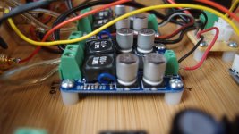
This is how I did it. The inductors are Wurth 74477110 10uH 5A, $2.12 from Mouser. I soldered a pigtail to one end, soldered to the tab and pressed down onto hot melt glue. I then soldered the other end directly to the pad. The inductors do not lay flat. This has to be done before attaching the terminal blocks. Also note that the terminal block through hole spacing for the power is tighter than the standard 5mm, which can be made to work, but I found some Phoenix ones with 2.54mm pitch for a better fit.
This is how I did it. The inductors are Wurth 74477110 10uH 5A, $2.12 from Mouser. I soldered a pigtail to one end, soldered to the tab and pressed down onto hot melt glue. I then soldered the other end directly to the pad. The inductors do not lay flat. This has to be done before attaching the terminal blocks. Also note that the terminal block through hole spacing for the power is tighter than the standard 5mm, which can be made to work, but I found some Phoenix ones with 2.54mm pitch for a better fit.
Attachments
Last edited:
For 8 ohm speakers you don't need high amperes, so the mss1048 of we pd in right size exist too. Capacitorfootprints are 8mm, maybe one can fit 10mm capacitors, but the 35v/1000uF FK's are 16mm, that is like half the ampboard
Here is how I do it:
An externally hosted image should be here but it was not working when we last tested it.
The FP series seem to have better specs than FK, particularly for RC (850 vs 600 at 220uF/35V size). The datasheet only has 220uF total here, the largest capacity FP at 8mm would be 220uF.
My advice to anyone f-ing with these boards is to leave the rail caps alone. After putting down a ton of heat to break the solder joints, pulling half the traces and, generally, creating a big mess, I think this is going to be an abandoned project. Not sure these are any better than my Sanwu TDA7498 and have been pretty much a headache to mod. The inductor mod was not nearly a problem. Not worth the effort in my opinion.
I wouldn't go for this "big" 10uF, better is higher resistance and lower value capacitor - in case of component size. (It's also better to have less capacitance when you deside to left the diode out.) I don't know if the "Giancarlo" mod is needing 10uF. 😵
You may go this way:
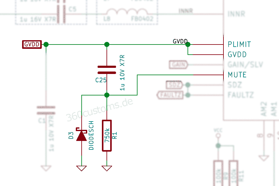
Diode is not "a must", but nice to have.
But all in all, doable. 🙂
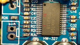
I need to implement your antipop-design, but I'm not sure how. I mean I find the corresponding pins from the board, but am I supposed to replace existing components or just add what you have here? I took a closeup about the situation so maybe you guys could help me.
And what about the used components? Is there some specific requirements for the resistor, capacitor and diode? Can i use a basic through hole-resistor and electrolytic capacitor?
Attachments
My advice to anyone f-ing with these boards is to leave the rail caps alone. After putting down a ton of heat to break the solder joints, pulling half the traces and, generally, creating a big mess, I think this is going to be an abandoned project. Not sure these are any better than my Sanwu TDA7498 and have been pretty much a headache to mod. The inductor mod was not nearly a problem. Not worth the effort in my opinion.
Seems like I'm the only one having problems desoldering the rail caps on this, so this is how I ended up doing it without lifting traces. I used my ChipQuik SMD1 kit, fluxing the solder joint, heating it up with a dab of the CQ solder on each side back and forth and eventually sliding (not lifting side to side) the cap off. I used 350C temp, though a higher temperature might work better, as the iron with chisel tip did spend more time on the joint than I felt comfortable with (maybe 10s), but with patience, each came off without lifting traces. I installed Panasonic FP 330/25V, these were the largest caps with an 8mm in that series. Measured ESR was .07 on these.
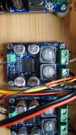
Finally mounted, wired and testing
Got everything mounted and wired. Testing went well, it worked! lol. These are stock Sanwu's, no mods yet as I wanted to be sure all my other hardware is correctly wired first. All good 🙂
Couple of observations, amps connected to Klipsch KSF 8.5, 8-Ohm speakers:
- no audio amp noise, noise is only observed when less than a foot from speakers, then only slight
- using a switch, mute pins make the speakers completely silent
- decent bass for tiny amps, powered by 24VDC up to 6A power supply
- mids & highs are crisp and clear (speakers are a big factor)
- iPhone 6+ can push the amps into thermal shutdown in about a minute
- Chromecast Audio can push amps into thermal shutdown in about 30 seconds
- Alexa won't respond if the music is cranked up, unless it's during a quiet passage 😉
Obviously, the enclusure needs top cover installed. That cover mounts the IEC 120VAC input socket (uses same cord/connector as desktop pc), which includes a fused, lighted switch.
Overall, very happy. Time for some mods and wire routing cleanup.
An externally hosted image should be here but it was not working when we last tested it.
You have no volume control?😕
Volume control is done by the streaming device, i.e., Alexa or Chromecast via mobile phone, or bluetooth receiver plugged into 3.5mm input jack. The amp is totally hands-free after power-up and the audio (volume and selection) is controlled elsewhere. Why add the complexity and possible noise source of a volume control?
Thermal shutdown ? With music ?
I can trip protection easily with music but never the thermal, I think that means above 150 degrees Celsius.
I can trip protection easily with music but never the thermal, I think that means above 150 degrees Celsius.
Thermal shutdown ? With music ?
I can trip protection easily with music but never the thermal, I think that means above 150 degrees Celsius.
Maybe I'm inaccurate, using wrong term, but the amps both shut down for a few seconds then came back on for a few seconds, then shut down for a longer time, then came back on, I left the volume unchanged through this until after second shutdown. I was playing the song Feel It Still, by Portugal The Man, modern alternative music. from my iPhone 6+.
Why add the complexity and possible noise source of a volume control?
Using "open" amplifiers has cost the lives of woofers in the past.
- Home
- Amplifiers
- Class D
- Cheap TPA3118D2 boards, modding them and everything that comes with it