I currently have 100 turns primary but that's too much wire loss because i was forced to use only 2x 0.35mm so that it fits in the core...
At 68 turns the switching transistors blow due to transformer saturation. With 3x 0.35mm i can do at most 17 turns per layer. Anything over 68 turns is going to require an extra 2 layers anyway so i want to play it safe.
At 68 turns the switching transistors blow due to transformer saturation. With 3x 0.35mm i can do at most 17 turns per layer. Anything over 68 turns is going to require an extra 2 layers anyway so i want to play it safe.
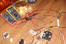
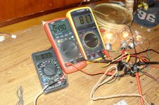
Ok, i think i've proven my point. Here's what my latest transformer does. 85 turns primary, 59 turns secondary, all with 3x 0.35mm wire. I dare anyone to try and shove more wire in that EI33. The DT838 on the left is measuring winding temperature btw. Do the math on the second picture. 🙂
This one doesn't get hot to the point you can cook eggs on it, but still enough for the tape to start melting, so i stopped after a few minutes. If i had proper high temp isolation tape it would probably be able to run continuously at this level, but again, it's meant for an audio amp so it'll do okay.
This one doesn't get hot to the point you can cook eggs on it, but still enough for the tape to start melting, so i stopped after a few minutes. If i had proper high temp isolation tape it would probably be able to run continuously at this level, but again, it's meant for an audio amp so it'll do okay.
Attachments
The wait is (almost) over!
I must say that i've learned more about SMPS than i ever wanted to. 😛 I've cleaned up my floor and set up a workbench with all the tools and electrical, scope, meters and so on. Right now i have a 100% working +/-80v SMPS in two transistor forward configuration (hence the high number of primary turns, but it's easier to drive than a half bridge) with TL494 and LM339. Switching MOSFETs are IRFP360s. Atm it is undervoltage/short circuit protected only, but the other protections are soon to follow.
Current status:
Amplifier PCB: 100%
SMPS PCB: 40%
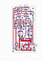
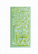
The PCB dimensions of the power supply have been fixed to 200x100mm. To keep things simple the control and protection circuits will be mounted on their own 50x50mm daughterboards, the input filter will also have its own PCB (well, i have a power connector with built in line filter so i will use that), and the standby supply will be on a separate board. The control circuit board is complete btw.
I can't give an ETA... but it's certainly not going to take long.
I must say that i've learned more about SMPS than i ever wanted to. 😛 I've cleaned up my floor and set up a workbench with all the tools and electrical, scope, meters and so on. Right now i have a 100% working +/-80v SMPS in two transistor forward configuration (hence the high number of primary turns, but it's easier to drive than a half bridge) with TL494 and LM339. Switching MOSFETs are IRFP360s. Atm it is undervoltage/short circuit protected only, but the other protections are soon to follow.
Current status:
Amplifier PCB: 100%
SMPS PCB: 40%
The PCB dimensions of the power supply have been fixed to 200x100mm. To keep things simple the control and protection circuits will be mounted on their own 50x50mm daughterboards, the input filter will also have its own PCB (well, i have a power connector with built in line filter so i will use that), and the standby supply will be on a separate board. The control circuit board is complete btw.
I can't give an ETA... but it's certainly not going to take long.
Its good news Th3 uN1Qu3, i`m slowly recover from health problem, soon will slowly update testing this amp. Take ur time Th3 uN1Qu3 😀
regards,
Azmi.
regards,
Azmi.
ok. here comp2...
I simulated this with LTSpice and got:
THD=0.38% for f=5kHz.
Not bad at all for a first attempt !
Did anyone build this (or a later version) ?
Yes, i've built it, norazmi also built it. I've also got a more powerful version in the works since like, um, forever...
I haven't given up on the project, it's just that i've had lots of stuff to do and i still don't have an adequate power supply for the thing... I'm working on that as we speak, but these weeks i've also got some exams that i've failed in the summer so i won't get too much tinker time. I hope to finish everything this year though.
I haven't given up on the project, it's just that i've had lots of stuff to do and i still don't have an adequate power supply for the thing... I'm working on that as we speak, but these weeks i've also got some exams that i've failed in the summer so i won't get too much tinker time. I hope to finish everything this year though.
Anyone here still using the AMP? Its over year now I am using it. these days the amplifier gets latched. To get it back working I have to switch it on and off. Also I noticed that this happens when there is no signal at the input.
hi....yes, i use it (sometimes)...because its my design 😀
and maybe a "latch" can happen, if comparator doesnt start work (= oszillation), because no signal to make a "first" switching action....
which parts you used? (show actual circuit dia. ...), then i can say more about it 😉
and maybe a "latch" can happen, if comparator doesnt start work (= oszillation), because no signal to make a "first" switching action....
which parts you used? (show actual circuit dia. ...), then i can say more about it 😉
hi....yes, i use it (sometimes)...because its my design 😀
and maybe a "latch" can happen, if comparator doesnt start work (= oszillation), because no signal to make a "first" switching action....
which parts you used? (show actual circuit dia. ...), then i can say more about it 😉
it starts to work but in sometime stops working. posting ckt diagram here.
Attachments
it will work ok, since me and Th3 uN1Qu3 made few modification on the circuit, i`ll post here if i find it, its long time ago we do that. if i`ve found it, i`ll post it here.
Hi all, this is old thread, is there anyone would like to continue experiment this module i`ll do test with my last schema and with help from others, Th3 uN1Qu3, Pafi, Luka and etc...
for now the lowet thd i have is 0.08% and i have good result with Ltspice including all necessary data and new pcb design. dc offset is about 30mv.
i really like to share this experience especially with Th3 uN1Qu3 😀
regards,
Azmi.
for now the lowet thd i have is 0.08% and i have good result with Ltspice including all necessary data and new pcb design. dc offset is about 30mv.
i really like to share this experience especially with Th3 uN1Qu3 😀
regards,
Azmi.
Here some contribution from me, simple class D and has been simulate with LTSpice with lowest THD 0.11 %.
Input Vrms 1.7v. Pow at output 24.4V 8 ampere. Power Rails +/- 45 VDC
mosfet use is IRF540N and IRF9540.
- Low noise while using comparator LM311 has been Improve.
- Low Thd has been Improve 0.11%.
- Input gain has been Increase.
Direct Newton iteration for .op point succeeded.
Fourier components of V(out)
DC component:0.023729
Harmonic Frequency Fourier Normalized Phase Normalized
Number [Hz] Component Component [degree] Phase [deg]
1 1.000e+02 1.097e+01 1.000e+00 -0.07° 0.00°
2 2.000e+02 8.637e-03 7.871e-04 -89.47° -89.40°
3 3.000e+02 4.580e-03 4.174e-04 -179.17° -179.10°
4 4.000e+02 2.230e-03 2.032e-04 -89.63° -89.56°
5 5.000e+02 3.487e-03 3.178e-04 -177.64° -177.57°
6 6.000e+02 1.984e-03 1.808e-04 -87.95° -87.88°
7 7.000e+02 2.196e-03 2.001e-04 -176.83° -176.76°
8 8.000e+02 1.434e-03 1.307e-04 -90.19° -90.12°
9 9.000e+02 1.243e-03 1.133e-04 -176.27° -176.20°
Total Harmonic Distortion: 0.101914%
Date: Sat Feb 18 23:55:32 2011
Total elapsed time: 483.297 seconds.
tnom = 27
temp = 27
method = modified trap
totiter = 5949112
traniter = 5949078
tranpoints = 1332273
accept = 935515
rejected = 396758
matrix size = 72
fillins = 135
solver = Normal
Matrix Compiler1: 11.4 KB object code size 11.8/8.8/[4.3]
Matrix Compiler2: off [5.6]/7.3/165.0


I have really enjoyed this project Please continue with it I would love to see it as a kit or get a pair of pcb's
regards Trev
regards Trev
Here some contribution from me, simple class D and has been simulate with LTSpice with lowest THD 0.11 %.
Input Vrms 1.7v. Pow at output 24.4V 8 ampere. Power Rails +/- 45 VDC
mosfet use is IRF540N and IRF9540.
- Low noise while using comparator LM311 has been Improve.
- Low Thd has been Improve 0.11%.
- Input gain has been Increase.
Direct Newton iteration for .op point succeeded.
Fourier components of V(out)
DC component:0.023729
Harmonic Frequency Fourier Normalized Phase Normalized
Number [Hz] Component Component [degree] Phase [deg]
1 1.000e+02 1.097e+01 1.000e+00 -0.07° 0.00°
2 2.000e+02 8.637e-03 7.871e-04 -89.47° -89.40°
3 3.000e+02 4.580e-03 4.174e-04 -179.17° -179.10°
4 4.000e+02 2.230e-03 2.032e-04 -89.63° -89.56°
5 5.000e+02 3.487e-03 3.178e-04 -177.64° -177.57°
6 6.000e+02 1.984e-03 1.808e-04 -87.95° -87.88°
7 7.000e+02 2.196e-03 2.001e-04 -176.83° -176.76°
8 8.000e+02 1.434e-03 1.307e-04 -90.19° -90.12°
9 9.000e+02 1.243e-03 1.133e-04 -176.27° -176.20°
Total Harmonic Distortion: 0.101914%
Date: Sat Feb 18 23:55:32 2011
Total elapsed time: 483.297 seconds.
tnom = 27
temp = 27
method = modified trap
totiter = 5949112
traniter = 5949078
tranpoints = 1332273
accept = 935515
rejected = 396758
matrix size = 72
fillins = 135
solver = Normal
Matrix Compiler1: 11.4 KB object code size 11.8/8.8/[4.3]
Matrix Compiler2: off [5.6]/7.3/165.0
can you please post the latest LTspice project file here?
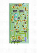
Thanks Azmi. Your PCB is a bit cramped though, most significantly there's no room for the output inductor which can get kinda big.
I haven't gotten around to building my updated, higher power version yet, tho i've had the PCB completed for ages. It's just that a lot of unfortunate events happened and i no longer have an oscilloscope, so i can't go in and build it with confidence. My old module still works just fine though, but its max supply voltage is limited by the 7812 and 7912 regs.
I haven't gotten around to building my updated, higher power version yet, tho i've had the PCB completed for ages. It's just that a lot of unfortunate events happened and i no longer have an oscilloscope, so i can't go in and build it with confidence. My old module still works just fine though, but its max supply voltage is limited by the 7812 and 7912 regs.
welcome back Th3 uN1Qu3.
Nice to hear that from you. allright i`ll modify little bit. for the inductor space and will post new pcb for it. Give me suggestion about the pcb and i`ll try to modified it. Th3 uN1Qu3, since i have 2 pcs prototype module, so after finish simulate with LTC i`ll do test in proto board. Yep i did try with irf240 and irfp240 but the thd will be high almost 1%, idk if its acceptable or not.
p/s - Aucosticraft, will post new schema with ltc after everything is done.
- Status
- Not open for further replies.
- Home
- Amplifiers
- Class D
- Cheap simple class D amp circuit to build.