aight, next time i`ll use N82 to record, seems 3110c picture is not clear and sound also low quality, becoz N82 is playing music while 3110c record it.
Try N93i. 😀 I have one but have bought other phones since because it's all beat up (that's how i got it), and a new body for it is like $80. But it's got an AWESOME camera, MPEG4 VGA res video recording with stereo sound, internet works quite well too, plus it allows you to use the very bright flash LED as a flashlight.
It's a brick of a phone but i liked it a lot. I do have a standalone Samsung digital camera but its sound quality sucks, it's only good for taking pics.
@ electroconico: If you're talking about the latest simulation posted by me, you go to View -> Spice Error Log. Be aware that if the time step is too large (and it is unless you explicitly set it) the distortion will show larger than it would really be in the physical amp.
For +/-47v rails, it would be 200-some watts on 4 ohms. Play around with the sim and see for yourself.
For +/-47v rails, it would be 200-some watts on 4 ohms. Play around with the sim and see for yourself.
Dear Th3 uN1Qu3 ,
1) What is the peak input voltage for undistorted output?
2) while working on second order output filter did you use specific calculation for L and C value? any specific type of filter like Butterworth or linkwitz... or..... cause that would decide whats linear, ie phase or attenuation.
3) the protection diode across mosfet plays special role here ? Or builtin protection diode is enough?
4) did you measure its bandwidth? because I think you are equipped for the measurements.
5) Any specific winding resistance of coil and ESR for cap?
6) Any spl words on the board design. if you have any thing to suggest.
Your work is really appreciable its neat and clean too.
1) Whatever you like, adjust the gain setting resistor to suit.
2) I tuned it for best compromise for all loads 8-4-2 ohm. The less the feedback loop has to do, the better the amp sounds. 22uH/1uF seems the best solution.
3) The protection diode does not handle any meaningful current. A friend of norazmi's drew them there and i just left them for the time being. My amp works fine without them.
4) Just barely, using the oscilloscope and RMS voltmeter. It's ok, no significant attenuation at 20kHz. I no longer have a high quality soundcard so i can't really do high accuracy bandwidth tests... but i'll try my best. I will do some tests once i finish the 350W version.
5) Depends on your load really. I use 3x 330nF polyester caps in parallel for the output filter, this has done nicely so far.
6) I'm still learning. But since i had a board that worked beautifully for the lower powered version i don't see why the slightly revised version (thicker traces and space for the 2nd p-mosfet) will not work as expected. I'll share the layout if it turns out okay.
I have done the first tests on the SMPS transformer that i wound. I used my square wave generator (fancy name for a 555, a high current MOSFET and a couple trimpots) to feed the switching MOSFETs, i set it to exactly 47% duty cycle at 100kHz. I tested the gate driver and MOSFETs without hooking up any power first. Sure enough, an ugly problem which pops up from time to time showed up. It's hard to explain in words and my drive circuitry is kinda weird (single nmos switching gate drive transformer, and only gate resistors on secondary, no diodes no zeners no nothing), but putting a ~100 ohm 1W resistor across the GDT primary fixes it usually, and it did fix it this time as well. Funny thing, same GDT, same MOSFETs, different power supply, worked just fine last month without the resistor...
Oh well. I put a lightbulb in series with the AC line, powered it up, scoped the secondary and i get a nice fat switching waveform. Now time for some random diodes, a random inductor and some random capacitors and i get a random power supply. 😀 😀 😀 Well, half a power supply to be precise.
And please no recommendation about gate drive circuits okay? The way i do it isn't extremely efficient but it works, gives a nice fat square wave, and most importantly, if the controller stops while the MOSFETs are still getting power, the gates are held at zero volts respective to the sources. With AC coupled GDT, if the pulse train stops, the gate goes to half the driver supply voltage... which means mosfets turn on, mosfets stay on, mosfets go boom. And double please no suggestions about IR2110 or similar. I built this class D amp so i don't have to use a driver IC, no way am i going to use one in the power supply.
And btw don't call work neat before you've seen it... But i'll post those pics soon enough. 🙂
Last edited:
Okay... This is um, weird. I expected something like 90 volts. I got 160! I double checked the math and the build. Everything's right. On load the voltage does start to drop but it's still over 100 with a 100 watt light bulb as load (obviously the bulb lights only at half brightness).
So what does this tell me? Looks like this will be a regulated supply after all... Well, semi-regulated. I only intend to limit the maximum idle voltage to +/-90v nothing more.
So what does this tell me? Looks like this will be a regulated supply after all... Well, semi-regulated. I only intend to limit the maximum idle voltage to +/-90v nothing more.
Of course, more challenges were waiting for me. I blew another two pairs of IRF740s... this time the 5A diodes were fine, so it was either the gate drive (unlikely), or...
As i found out quickly the transformer was saturating. So i skimmed thru my books again and quickly noticed that "without an airgap the maximum practical flux swing in a forward converter is 1000G. That is 100mT. My calculations were done with double that... 😱 and there's no room for extra wire.
Then of course our good old friend the airgap enters the scene. Fortunately i still had a pair of those lying around. As you can see they are designed for single transistor forward converters so their RDSon is quite high, but the TO-247 package would (hopefully) keep them from blowing up, and indeed it did.
I kept folding that piece of paper and increasing the gap till the core no longer saturated, i think that now i have something crazy like 2mm. But does it do 400 watts now? Just barely... The MOSFETs stay cool, but the core gets very hot. At least nothing blows up anymore. 🙂 Mind you, my load resistor is 4.7 ohms so i was also going over the designed current, it should behave a little better in the amplifier.
Certainly it does enough to keep the "music power" crowd happy. 😀 I know i had a pair of larger cores around but i can't find one of them, so this'll have to do. You know those junk ATX power supplies that use the EI33 core, all of them blow at 250W. At least i have managed to do better. 😀
Hi Th3 uN1Qu3, which schematic you`re using to build smps, i`ve few schematic that i build it with success complete with winding transformer calculation, so far i dont build permanent smps because i dont have protection scheme yet, ie. overcurrent, over voltage, etc. Only have protection with fuse. 2-3 days more i`ll have enough time to construct amp with 2 ohm load.
i`m just thinking about -+ 9v supply using zener diode so we dont need to have external supply, maybe seperate supply for lm311 + tl071 and another one is for bipolar transistor. as we can see on lt spice simulation, both bipolar transistor will draw more than 500 ma current, what about replace them with bd139 and bd140?. i`ll do some test with it. so far this amp have low thd and quite powerful with only irf540 and irf9540 and 4 ohm no problem with this amp, 2 ohm not yet tested, will do soon.
regards
Azmi
I think BD139 and BD140 do not have enough gain at this frequency so the comparator will no longer be enough to drive them... There are TO-92 devices capable of 1A.
My transformer still isn't behaving so i decided to go the next size up and use a pair of ER-35 as i found the second one. This one will fit enough wire to run at a lower flux density, no more saturation problems. 🙂 I'm not using a schematic, i'm making it up as i go.
My transformer still isn't behaving so i decided to go the next size up and use a pair of ER-35 as i found the second one. This one will fit enough wire to run at a lower flux density, no more saturation problems. 🙂 I'm not using a schematic, i'm making it up as i go.
😀, so you build your own 😀 . I dont have experience like u 😀. Th3 uN1Qu3 your smps include protection? can u make it? hmm which to-92 device can provide 1A and have enough gain for the comparator? can u make a suggestion? i have with me few model to-92 transistor, c1815, c2240, c945, 2n5401, bc546, mpsa42, mpsa06, 2n2907, 2n2222, c9012, i have match npn and pnp for each of them. The important like u said they must have enough gain for lm311 freq. can u give me suggestion about it? which transistor is suiteable for it and important to deliver at least 1A current.
regards,
Azmi
regards,
Azmi
😀, so you build your own 😀 . I dont have experience like u 😀. Th3 uN1Qu3 your smps include protection? can u make it?
Yes, it will have overcurrent, overvoltage and overtemperature protection. Overcurrent will use 0.01 ohm sense resistors for each rail, those are easily made by putting 10x 0.1 ohm in parallel (the lowest value which i can find around here).
I have also wound a new gate drive transformer on EE19/8/5 core (from ATX PSU standby circuit), it looks so small and cute. 😀 It works great. Windings are 50+50+50 turns with 0.3mm wire.
If you want to make your own it goes like this: Wind 50 turns (with 0.3mm you can fit exactly 25 per layer in this core so that makes it two layers, one on top of the other, no insulation needed between those two layers), this will be one of the secondaries. Put 2-3 layers of insulating tape over. Wind another 50 turns, this will be the primary. Put another few layers of tape over it. Wind the last 50 turns, this will be the other secondary. Then add another layer of tape, assemble the core and glue everything together.
This applies for the two transistor forward configuration which i will be using for this supply. Now i'll be winding the main transformers.
I'll look at the transistors later.
Great 😀. i have many broken psu, im working as computer technician here, i think i can get small core EE19. Completely understand about the driver transformer that u explain here. If u have free time could u send me a copy of your smps including pcb design ( if u dont mind ) to my email becoz i want built it, i have many big E core here, can be the main trafo so working freq 100khz would be less winding as i already build smps work at 75khz. Im thinking of smps because linear transformer is heavy like i have here 40 0 40 vac 12 amp about 5 kg lol 😀 . sometimes its hard to find a case suitable for this transformer.
regards,
Azmi.
regards,
Azmi.
When it gets done it'll be posted here. I have many broken PSUs too but it seems they aren't too much use for big powers (well, they broke for a reason didn't they).
The bad news: The two cores weren't the same size. So i proceeded to wind another EI33 core that operates at lower flux density. And it still saturates... blowing FETs up is fun sometimes but it gets boring quickly. Somehow i have the feeling that i've been looking at the wrong datasheet. Sure, all the physical sizes line up, but the ER35 core which is obviously larger, has a lower effective area in the datasheet than the EI33. Something isn't right.
The good news: I have an ETD49 and now i have a good excuse to use it. Should do 1kW without blinking. 😀 So much for kiddy chinese PSU ferrites.
Well, the ETD49 wouldn't fit the case i want to use for my amp, unless i put it on a side. This didn't appeal to me very much, and third time lucky they say. I decided to give the EI33 core a final shot, at even lower flux density.
I ended up with the following configuration. 100 turns primary, 68 turns secondary. Wound as follows: 50 turns primary with 2x 0.35mm wire, 13 turns secondary with 3x 0.35mm wire (for the tap for feeding the 12v linear regs), the remaining 55 turns secondary with 2x 0.35mm wire, and finally the last 50 turns primary with 2x 0.35mm wire.
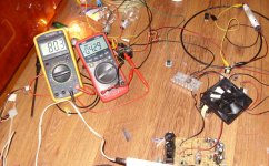
I knew the copper loss was going to kill me on this one. But a hot transformer is still better than blown MOSFETs. And... results? See for yourself.
And yes, talk about a messy floor. At the moment the whole thing is being driven from an adjustable generator using a 555, a couple trimpots and a MOSFET for driving the GDT, no TL494, no feedback, no nothing, all is controlled by hand. 🙂 The fan is a 24v 92mm fan being run at 12v so it doesn't move as much air as you could imagine. The heatsink holding the MOSFETs stays cool, the transformer is at about 50C estimated, i'll probe it with the thermocouple later.
You can see the primary caps at the bottom (two 680uF 200v caps in series), the tiny GDT, the crap diodes which i took from the worst of ATX supplies (200v 3A, and actually they're quite well suited for this job), output coil (which btw is taken straight from an ATX supply, i'm using the 5v windings in series, and it runs extremely hot, actually the reason it's sitting on another coil is because it got so hot that it started to leave hot glue on my floor! 😱). The tin which didn't make it in the pic in whole, is filled with water and is holding some of the (undersized) load resistors to keep them from burning up. Romanian load testing at its finest. 😀 The secondary caps are currently 2x 330uF Viva... anyone remember them? 😀
And yet, with all of this, i'm getting 350 watts. 🙂 I expect at least 20W more from a proper output coil, some 5W from better rectifiers, again a few more watts from beefier caps... and looky, there's my 400W. And all ATX PSUs which use this core blow up at 250W. Romania 1, China 0. And btw, the switching devices are a pair of those - based on their voltage rating (220v mains here), they should have blown in the second the supply was plugged in - but apparently nobody told them. 😀 The primary diodes are some 5A ultrafasts from Central, don't remember their exact model.
I'll be dealing with the output coil now, then winding the second transformer, then i'll get to designing a proper control circuit. 🙂
I ended up with the following configuration. 100 turns primary, 68 turns secondary. Wound as follows: 50 turns primary with 2x 0.35mm wire, 13 turns secondary with 3x 0.35mm wire (for the tap for feeding the 12v linear regs), the remaining 55 turns secondary with 2x 0.35mm wire, and finally the last 50 turns primary with 2x 0.35mm wire.
I knew the copper loss was going to kill me on this one. But a hot transformer is still better than blown MOSFETs. And... results? See for yourself.
And yes, talk about a messy floor. At the moment the whole thing is being driven from an adjustable generator using a 555, a couple trimpots and a MOSFET for driving the GDT, no TL494, no feedback, no nothing, all is controlled by hand. 🙂 The fan is a 24v 92mm fan being run at 12v so it doesn't move as much air as you could imagine. The heatsink holding the MOSFETs stays cool, the transformer is at about 50C estimated, i'll probe it with the thermocouple later.
You can see the primary caps at the bottom (two 680uF 200v caps in series), the tiny GDT, the crap diodes which i took from the worst of ATX supplies (200v 3A, and actually they're quite well suited for this job), output coil (which btw is taken straight from an ATX supply, i'm using the 5v windings in series, and it runs extremely hot, actually the reason it's sitting on another coil is because it got so hot that it started to leave hot glue on my floor! 😱). The tin which didn't make it in the pic in whole, is filled with water and is holding some of the (undersized) load resistors to keep them from burning up. Romanian load testing at its finest. 😀 The secondary caps are currently 2x 330uF Viva... anyone remember them? 😀
And yet, with all of this, i'm getting 350 watts. 🙂 I expect at least 20W more from a proper output coil, some 5W from better rectifiers, again a few more watts from beefier caps... and looky, there's my 400W. And all ATX PSUs which use this core blow up at 250W. Romania 1, China 0. And btw, the switching devices are a pair of those - based on their voltage rating (220v mains here), they should have blown in the second the supply was plugged in - but apparently nobody told them. 😀 The primary diodes are some 5A ultrafasts from Central, don't remember their exact model.
I'll be dealing with the output coil now, then winding the second transformer, then i'll get to designing a proper control circuit. 🙂
Attachments
Last edited:
Hi Th3 uN1Qu3, good to see and hear about your smps result test, and ur using NE555 as a generator? what about working freq on ur smps? I think your result seems right, with IE33 core it will be little hot as it handle power more than 300 watts 😀 . and the coil from 5v supply smps of course cant hold the power 😀 lol. iave experience with that core from 5v supply before, it will become hot fast and i change to t106-26 yellow white one and its fine with 30 turn for each rails.
well im happt with your progress on smps and of course your contribution, your time, skill to share here, i`ve test with uc3842 before but not good result and i`m lack of experience of smps and knowledge, and i`ve got click sound at rail supply with uc3842, i think maybe not enough winding on primary and secondary of the core. Btw i`m happy with your progress 😀 . please include the winding calculation too for the core 😀.
regards
Azmi.
And about this amp, i already test with 8 ohm and 4 ohm and it can drive it easily with that load, i dont test it yet with 2 ohm and bridge mod, as i have 2 board now, ill test it on bridge mode, with your configuration 22uh and 1uf filter cap. now im working on my regulator for +-9vdc supply ( this regulator is from ESP website ). I need to make new one, becoz old one i give to my brother for his final semester project ucd amp. The project is success with 3 hrs presentation and hes lecturer wanna buy the whole thing from him including circuit and etc...
regards,
Azmi.
regards,
Azmi.
Hi Th3 uN1Qu3, good to see and hear about your smps result test, and ur using NE555 as a generator? what about working freq on ur smps?
Frequency is 100kHz as i stated. The core probably takes more flux at 75 or 50kHz, but i would have ended with the same amount of wire anyhow... and needed a bigger output inductor and caps for the lower frequency.
iave experience with that core from 5v supply before, it will become hot fast and i change to t106-26 yellow white one and its fine with 30 turn for each rails.
I have a bigger toroid from an Antec PSU, i think it's T130-52, i will be using that and filtering both + and - rails with it so that the DC bias cancels itself out... should run a lot cooler that way.
i`ve test with uc3842 before but not good result and i`m lack of experience of smps and knowledge, and i`ve got click sound at rail supply with uc3842
UC3842 is a current mode controller and needs more careful calculations.
please include the winding calculation too for the core 😀.
I have a spreadsheet that i made myself. It'll be posted - just need to implement a few more variables like voltage drop of transistors and winding resistance. Other than that it calculates just about everything one would need when designing a two transistor forward SMPS. I'm especially proud of the temperature compensated wire resistance calculator - it tells you the worst-case power loss of a specified length and diameter wire at a specified temperature rise. Supports multi stranded wire too. 🙂
I need to make new one, becoz old one i give to my brother for his final semester project ucd amp. The project is success with 3 hrs presentation and hes lecturer wanna buy the whole thing from him including circuit and etc...
That's what you call a successful project. 😀
Th3 uN1Qu3, thought of using 3524 it has built-in everything you need. and easy too, cost here is $0.5.
Some good links for you.
http://www.smps.us/magnetics.html
http://www.intusoft.com/mag.htm
http://www.rale.ch/demo.htm
Some good links for you.
http://www.smps.us/magnetics.html
http://www.intusoft.com/mag.htm
http://www.rale.ch/demo.htm
Last edited:
SG3524 doesn't have anything extra compared to the '494... Anyway, i'll be making yet another transformer. 😀 This one does 400W but you can cook eggs on it... it's an accident waiting to happen.
Since with every transformer i wind i'm getting better at shoving impossible amounts of wire in this tiny core, i'll be trying to get 85 turns primary/60 turns secondary with 3x 0.35mm wire for all windings.
The last link looks interesting, thanks.
Since with every transformer i wind i'm getting better at shoving impossible amounts of wire in this tiny core, i'll be trying to get 85 turns primary/60 turns secondary with 3x 0.35mm wire for all windings.
The last link looks interesting, thanks.
- Status
- Not open for further replies.
- Home
- Amplifiers
- Class D
- Cheap simple class D amp circuit to build.