Good job norazmi.
I guess i've been delaying this for too long with no excuse, so next week i'm buying another spool of wire and starting work on the SMPS. I will be doing an unregulated 70-0-70v supply (hey, if i have to buy 200v power mosfets anyway why not get the most out of them). I have studied control loop compensation and made some nice spreadsheets to help in calculating compensation components, but i feel that such complication is not needed for this purpose because all it would do is limit power on a 8 ohm load, which is what i'll be using the amp on mainly. An unregulated SMPS with a PFC stage before it sounds like a good idea tho, but i want to keep it simple first time. To control bus pumping i will have two separate transformers, one for each rail. That also owing to the fact that i have lots of EI33 cores and just a few bigger ones, that i want to use for other projects.
Because simply put, high voltage P-channel mosfets suck, i will be doing something unconventional and using two P-channel devices in parallel and only one N-channel. I will also be experimenting with various gate drive resistors and zener diodes and measuring losses for all combinations. 🙂 Either way, power stage losses sim unreally low, but we all know that the practical world isn't that kind so we'll wait and see. 😛
To be continued soon.
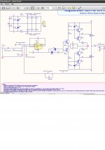
nice to hear that, btw like u said, P-channel mosfet suck, damn. And of course having problem with bass pumping, i`ve read from ejtagle at forosdeelectronica.com about the supply voltage at LM311, and the supply only +-3v and the reason about this voltage is about to have clear sound and not too much bass at output. i`ve schematic hes using only lm311 and no TL071 opamp. I`ll post some schematic here.
The TL071 is there just as a buffer... It's a good idea to include it because not every signal source will be able to drive the LM311 properly. I also think it can be used (to some degree) for canceling the DC offset on the output.
I'm still wondering what i'm gonna do with the old board. I'm probably going to give it away to a friend that's more into microcontrollers than power electronics, a change in his hobby should be good for him. 😀
I'm still wondering what i'm gonna do with the old board. I'm probably going to give it away to a friend that's more into microcontrollers than power electronics, a change in his hobby should be good for him. 😀
I have another idea for the DC offset. But for now i'm very busy with output inductors. I finally built a test jig around my oscilloscope to measure inductance, and i discovered some nasties in the current output filter (which explain why the treble response sucked). I'll explain in more detail in an hour or so.
Since besides this inductor which i'm currently using all i have is -26 and -52 cores i'll be busting out the hacksaw and cutting some gaps. 😀 Now i just have to buy a few extra parts to measure saturation currents as well and i'm in business.
Since besides this inductor which i'm currently using all i have is -26 and -52 cores i'll be busting out the hacksaw and cutting some gaps. 😀 Now i just have to buy a few extra parts to measure saturation currents as well and i'm in business.
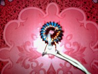
aight, i`ll post some picture the best filter i`ve made using ferrite toroid from car smps, i do gaps about 2 mm, that the first inductor i`ve made using class D amp, i think its material 77, but now im using t106-2 from amidon, the ferrite warm a little when full power but sounds good enough.
It's normal for it to warm a little. How many turns do you have on it?
Anyway. My "magic" inductor turned out to be 52uH. Which coupled with the two 330nF caps in parallel is already 5dB down at 20kHz on 4 ohms... there i have my treble problem. The core that i gapped ended up still having too high of an AL value so it still saturates and heats up like crazy. It is a small core tho (like T80 but thicker)... time for some bigger ones. 😀
After a few more calculations i decided to go with 12uH/990nF (adding a third 330nF cap). This will enable good response on all loads 8-4-2 ohms. It is 1.5dB up at 20kHz on 8 ohms, .82dB up at 20kHz on 4 ohms and 1.1dB down on 2 ohms. Good enough.
Edit: Seems like this small of an inductor would let too much residual ripple get to the speaker... more work to do. 😛
Last edited:
ive wound about 18 turns, i`ll upload some photo, this one is the best i`ve made, i need to wait my inductor meter to measure it. 😀
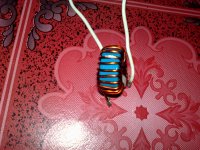
ive wound about 18 turns, i`ll upload some photo, this one is the best i`ve made, i need to wait my inductor meter to measure it. 😀
Use arta LIMP to measure inductor. if you are already using it. I use the same.
My "magic" inductor turned out to be 52uH. Which coupled with the two 330nF caps in parallel is already 5dB down at 20kHz on 4 ohms
Was it measured or calculated?
I never liked ARTA. For now i am using my oscilloscope with the parallel resonant circuit method, and in a few days i'll go get the extra parts that i need to measure saturation current as well.
52uH measured, 5dB down is based only on filter response, feedback fixes some of that, but high frequency sinewaves showed consistently lower in level both in simulation and in the real thing. Not 5dB lower but certainly there is a difference.
I have never done an actual frequency response test on the amp but will do soon. Edit: @ norazmi: 18 turns on T106-2 is just 4.4uH which explains why it is getting hot. I also believe that while your woofer won't mind, a midrange or a tweeter won't really like the amount of residual that your inductor lets thru. Try 40 turns (22uH) and the heating should go away.
Last edited:
okie, i`ll do that 40 turn, its suiteable to drive 2 ohm load? what is your suggestion for lc filter plus caps, 22uh 680nf can drive 2 ohm? btw i`m waiting to follow your result and wanna mode it as well, i`ve 2 board already etch and run and not mount it yet. will do after your experiment 😀.
22uH (40 turns)/1uF should work great for all loads.
I'm still gapping a T94-26... well to be more specific two of them glued together. With four gaps ~2mm wide the AL value was still too high at 40. It seems each pair of gaps drops the AL value by 20 so six gaps which i have now should be enough, as according to Micrometals' calculator, AL value for two T94-2 stacked is 17. I'm going to wind it and test it now.
This is for my current board, will probably do 150W on 2 ohms if i bump the power supply up a little, but i doubt this core will be good for more than 200W simply because thick enough wire won't fit.
For the 320W/4ohm powered by +/-70v i will be using T106-26, more gaps, more fun. 😀
Edit: -2 material is supposed to be painted RED... Is yours solid blue? If so, that's -1 material. Try 28 turns. There's a little piece of software called Mini Ring Core Calculator which you can use to find the number of turns.
Last edited:
allrite, oh nope Th3 uN1Qu3 , the blue one is ferrite toroid from car smps, Th3 uN1Qu3, can i have your email address, regarding simulation u post here earlier i do make some modification that reduce thd up to 0.04%, i want to send it to u to verify my modification on your simu was ok or not. its really low thd but having some problem with bass pumping.
22 uh / 1uf i must try this with 2 ohm load tomorrow and i`ll post some video when its playing. the blue ferrite toroid size same as t106-2 size but its use less cooper than t106-2 and its 16awg cooper on it. 😀
22 uh / 1uf i must try this with 2 ohm load tomorrow and i`ll post some video when its playing. the blue ferrite toroid size same as t106-2 size but its use less cooper than t106-2 and its 16awg cooper on it. 😀
My address is the same as my username just replace the space with _ and add @yahoo.com
Anyway. I finished gapping the T94-26. 7 gaps in total. I wound it with 30 turns (more wouldn't fit), 20AWG wire from an ATX power supply. I know this wire sucks because the plastic insulation takes up a lot of space, but i have lots of it so it was worth a shot.
Inductance came up as 21.6uH. Perfect. 😀 The amp must really like it because the DC offset dropped down to 13mV! At first i thought my meter broke but it really is that little. The core doesn't heat at all.
On the bad side, now the top of the waveform clips quite a bit earlier. P-channel mosfets suck. This, and bus pumping makes the positive rail go down to 26 volts while the negative gets bumped up to -32.5, limiting the max clean output to 15.5v RMS on 4 ohms which is 60 watts. Darn. I thought it was the transformer because it originally had one 45v winding and i split it by eye, but reversing the AC input to the bridge rectifier did nothing. I think i will make the negative rail slightly higher in the SMPS.
Edit: Caught it. The reason is high impedance in the power supply, aka flimsy wiring. Looks like the 20AWG doesn't cut it anymore even though it's barely half a meter long. The positive rail was wired with 20AWG while the neg was wired with 18AWG... this is where the imbalance comes from. I'll beef up the wiring and report back.
Last edited:
Allright, thanks for the email dude.
how do you make 7 gaps? one core having 7 gaps?. with 21.6uh of inductor feed with 1uf caps?? the core does not heat thats good news 😀.
lol you wound liner transformer by yourself? cant imagine that lol, it must be long coil wire arround you 😛. regarding bass pumping, what about if we put 1uf caps for each rails close the mosfet and 1uf feed with +v -v rails?. i`ve tried before feed smps with ucd by ejtagle, ucd suck lots of current from smps but smps can operate with normal operations not too hot its middle when full power.
Do you think cable size is matter? I think its about cable size how much ampere it can handle and how smooth current flow through em.
regards.
- Status
- Not open for further replies.
- Home
- Amplifiers
- Class D
- Cheap simple class D amp circuit to build.