BrianGT said:The group order deadline is a week from tommorrow.
But the deadline to request to be added to the buy is already passed.
screw description
Peter,
I don't mean to be a PITA but how are the screws described - so that I know what to look for?
Thanks!
Peter,
I don't mean to be a PITA
but how are the screws described - so that I know what to look for?Thanks!
But the deadline to request to be added to the buy is already passed.
I think he will still honor orders. The deadline was to get the price list. I will e-mail to e- lizard if he needs it
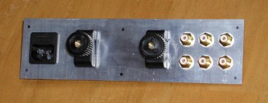
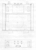
I changed the layout for the rear panel, accomodating the new boards and providing more of a dual mono setup (at least for the outputs). I found no way to achieve dual mono setup for the RCA inputs, as first, they should be closer to the source selector switch and secondly, I really wanted to place AC connection on the rear panel, as this is much more universal (and convenient) than doing it from the bottom. The AC socket is sourced from Digi Key and it is a snap in type (very nice, actually). It is also further away from the rest of the circutry, so some of you might be more happy about that.😉 The fuse holder is integrated, so no need for additional hole in the bottom, less wires, less soldering.
There will be still an option for blank panel and only 2 RCAs. Any other requests have to be specified when ordering, but no additional holes would be made.
There will be still an option for blank panel and only 2 RCAs. Any other requests have to be specified when ordering, but no additional holes would be made.
Attachments
Re: screw description
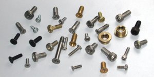
Here's the screws I use most often. The ones with square heads are called Allen screws and are more or less industry standard for audio equipment. Most of the other screws in a pic are used in aircraft industry, and might be harder to source. As to the countersunk screws, I like the ones that require rather shallow countersink, so the head is not that big.
bpetrus said:Peter,
I really like the screws you are using for the chassis! What supplier are you using for these?
bpetrus said:Peter,
I don't mean to be a PITA
Thanks!
Here's the screws I use most often. The ones with square heads are called Allen screws and are more or less industry standard for audio equipment. Most of the other screws in a pic are used in aircraft industry, and might be harder to source. As to the countersunk screws, I like the ones that require rather shallow countersink, so the head is not that big.
Attachments
Looks great Peter!
The last few pictures have convinced me to get in on the order...
One comment: could you turn the binding posts 90 degrees? I have speaker cables which are too stiff to fit between the posts or between the posts and RCAs / IEC entry. If the binding posts were horizontal, the cables can approach from above or below, and this is much easier to connect. As wel, if the posts are near the top of the panel, this provides more room for a bend radius in the cables to approach from below, against a flat surface (floor / shelf). I must not be the only one with stiff cables... ?
And one question (maybe this has already been asked): do the cardas CCBP / CCGR binding posts fit in the same mounting holes as the patented posts you've shown here?
Was going to ask same question about binding posts .Also would like them turned 90 deg. if possible everything else looks great
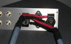
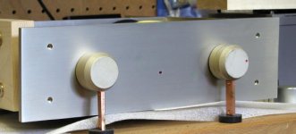
I gave much thought as to the best layout for the rear panel and it seems to me that this one is the most practical. The speaker cables were not supposed to be routed to the outside (from the binding posts), but to the inside. This way, maximum clearance and flexibility can be achieved and if you have really stiff cables it is much easier to run them to the side than to the bottom.
I used the old panel in a picture (so disregard AC socket). The spacing between posts is 2.7 and on the most recent design, I have 2.9" of spacing (which is even more than in this pic). If I install the posts horizontally, the clearance to the bottom is only 2.5".
There is always an alternative to not having holes for binding posts made, and anyone can make their own choices on that.
The most important issue here is, that if I position posts horizontally, I will not have enough space for BG caps ( it will be probably OK with Panasonics) and I don't want to extend the chassis by another 1/2". If mounted this way, there is no problem with clearing the caps and wire connections from the board to the posts have minimum distance.
Attachments
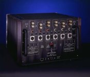
Look at this picture of Jeff Rowland multichannel amp. He could easily position the posts horizontally, yet for some reason (even with so tight spacing) they are mounted vertically (like in all their amps)
http://www.jeffrowland.com/model_112_photo_2.htm
http://www.jeffrowland.com/model_112_photo_2.htm
Attachments
Will the Cardas CCBP/CCGR fit the cutouts of the patented version which would be 1/2" diameter holes on 3/4" centers I believe just asking because I have several piars of these waiting to be used.
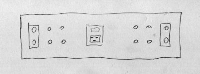
Hmm... well, considering I'm quite partial to symmetric layouts, and not at all partial to rotary switches or attenuators, I guess I'll go for the undrilled back panel, and do a layout as shown below. Input switching would be by relay, and volume control could be either PGA2310 or a relay network like this one.
Attachments
This way, the binding posts will go where a side-approach cable can fit nicely. Bear in mind, this means the undrilled panel will also have to omit the two screw holes which attach into the thick center piece, which, I suppose, could also be eliminated in my case.
The looks will be good, but it will make the wiring longer than Peter's design. Remember why ppl use direct soldering in the first place?
hifiZen said:This way, the binding posts will go where a side-approach cable can fit nicely. Bear in mind, this means the undrilled panel will also have to omit the two screw holes which attach into the thick center piece, which, I suppose, could also be eliminated in my case.
It would be even better to follow with this type of layout, which is true mono and somhow more elegant. If using relays for switching, keeping source connections separate and wires short is no problem
This is what I would do myself, if I didn't want to keep the overall design simple (rotary switch with RCAs wired directly).
In your case, mounting the boards on the sides is fine too, and you don't need the center piece either. If there is enough interest in that type layout, I could provide it as well (at least 20 pcs)
All Cardas binding posts are interchangable. It means regular style fits the holes of patented posts, the only difference is that patented post has addtional 1/4" mounting hole in the center.
Attachments
I'll be ready any time now, I'm only waiting for the web site to be arranged.
I received quotation yesterday and it's in line what I expected. I upgraded some panels and materials.
Front panel will be 3/8 thick, rear panel is 3/16". The heatsink assembly (3 x 2 x 0.50 bar) will be made out of copper for better heat transfer and possible gains in sound 😉
Only the outside panels are brushed, everything is clear anodized. I will supply all the screws and stand offs necessary for construction.
The unfinished chassis is $15 less than a finished one, so I don't think it's worth to bother with that option.
The finished chassis, as promised, is $150 USD (this include my local, 15% taxes).
The price is valid for this forum group order only. If ordered later, it will be approx. $200 (and still available from my upcoming website).
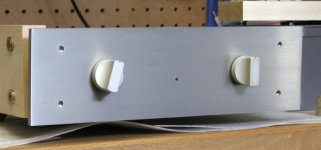
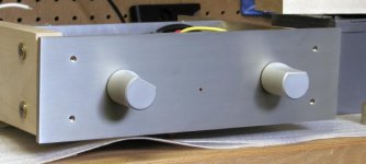
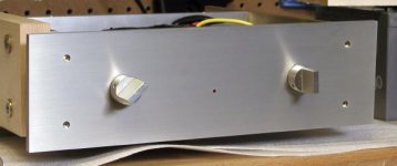
Since at least 50 chassis unit will be ordered, it means that 100 knobs are needed as well. I did some research today and here are some suggestions. Please comment as to your preferences.
Those knobs are from older ML preamp and are currently my favaourites, both in terms of appearance and functionality. 1" dia. but can be made in any size.
Those knobs are from older ML preamp and are currently my favaourites, both in terms of appearance and functionality. 1" dia. but can be made in any size.
Attachments
- Status
- Not open for further replies.
- Home
- Amplifiers
- Chip Amps
- Chassis for a group order of non-inverted GC kit?