Hi Gaborbela,
Good to hear from you!
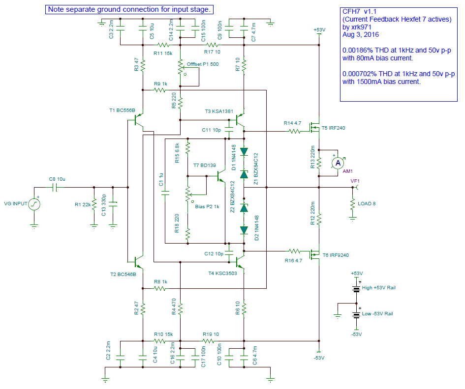
This amp layout is made for hexFETs. So GDS pinout. Are the Toshiba’s lateral FETs ?
Good to hear from you!
This amp layout is made for hexFETs. So GDS pinout. Are the Toshiba’s lateral FETs ?
Thank you!
The Toshiba pins (100%)match the hexFet pins and those are Audio mosfets all do nowadays hard to find them!
I have some at home.
Please do not mix those with the Hitachi, Exicon, etc laterals.
The Toshiba pins (100%)match the hexFet pins and those are Audio mosfets all do nowadays hard to find them!
I have some at home.
Please do not mix those with the Hitachi, Exicon, etc laterals.
Ok - neat. Which Toshiba part number is this? I am unfamiliar with big Toshiba MOSFETs except the smaller unobtanium TO220’s that have been popular as drivers in some amps of late.
2SK1530 & 2SJ201 or 2SK1529 & 2SJ200, there are some older similar types.
The truth is hard to find them but it brings improvement compare to the hexFET.
The truth is hard to find them but it brings improvement compare to the hexFET.
I’ll have to keep an eye out for those. Although, I seem to have pretty good results with Fairchild FQA40N25 and FQA36P15 which sound very good, are robust and cheap as chips ($7/pair from Mouser).
Last edited:
Originally Posted by zoky2 View Post
apexaudio,
I replaced 6k8 resistor with 12k and still no change . Something other must be wrong
Regards
zoky2
XRKaudio wrote:
Did you ever resolve the lack of bias issue?
Yes, I was resolve bias issue,but I can t remember how exactly I do this.
It was something with 100k trimers T1 and T3 and some voltage across them.
Sorry ,I can t remember anything else.
Regards
zoky2
No worries. Just wondering if that last layout by Thiago is good to go. If anyone else has built it and got it to work please let me know.
Sorry I developed this back when I was using Tina. I have since switched to LTSpice but never made this one. It’s easy enough to make from the schematics. All common parts.
I know ..
But I'm completely new in LT Spice ^^
Schematic ist built. But results are Bad.
I think IT IS an Error in config of Simulation.
Parts are ordered 🙂
But I'm completely new in LT Spice ^^
Schematic ist built. But results are Bad.
I think IT IS an Error in config of Simulation.
Parts are ordered 🙂
Last edited:
hi
fixed ... one part has a value of 0,22 instead of 0.22 or 220m
german "," instead of "." 🙄
fixed ... one part has a value of 0,22 instead of 0.22 or 220m
german "," instead of "." 🙄
yes i tried these changes.
FFT looks a bit weird but this is a FFT-setup problem i think.
I added cap multiplier ( power supply )
and want to see hat happens and what is the difference
and use a cap multiplier instead of diode + 10Ohm
i will understand the functionality of current feedback amplifiers ...
FFT looks a bit weird but this is a FFT-setup problem i think.
I added cap multiplier ( power supply )
and want to see hat happens and what is the difference
and use a cap multiplier instead of diode + 10Ohm
i will understand the functionality of current feedback amplifiers ...
Perhaps you should try the Thiago layout with all corrections and built in cap Mx?

Schematic:
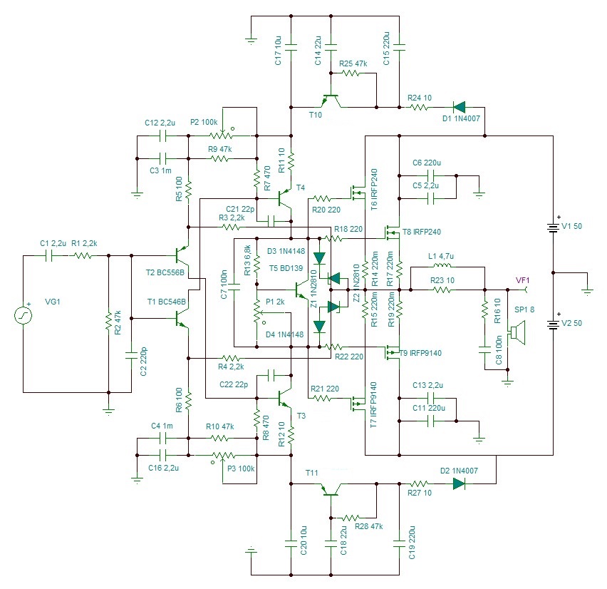
Gerbers:
https://www.diyaudio.com/forums/attachments/solid-state/621480d1497647661-cfh7-amp-cfh9cx-zip
Schematic:
Gerbers:
https://www.diyaudio.com/forums/attachments/solid-state/621480d1497647661-cfh7-amp-cfh9cx-zip
Last edited:
file attached
idea is to to use the same pcb and heatsink for one channel
i hope PSRR is better
i dont have a "poti" in library so i use a second resistor
I didn't know this Design until now ...🙄
idea is to to use the same pcb and heatsink for one channel
i hope PSRR is better
i dont have a "poti" in library so i use a second resistor
I didn't know this Design until now ...🙄
Attachments
Last edited:
Didn’t know of Thiago CFH9 with Cap Mx? I have not personally built that yet so you might be the first verification build as far as I know. The thread has been cold for a while. Thanks for reviving it.
Last edited:
Hi Saddevil,
I took your LTSpice file and modified the FFT analysis part to use V(out) label. Changed the gate snubbers from 22 ohm to 220ohm. Otherwise the schematic is the same.
It runs fine and a nice performance: at 72Wrms (68Vpp) into 8ohms has
predicted 0.00123% THD and nice harmonic profile. Dominant third order and
descending higher orders. This will only be true if parts are matched but in reality, MOSFETs and other parts are not matched above and below so THD will be a bit higher and distortion profile may end up being dominant 2nd order (a good thing).
Here is predicted FFT:

Revised .ASC file attached.
I took your LTSpice file and modified the FFT analysis part to use V(out) label. Changed the gate snubbers from 22 ohm to 220ohm. Otherwise the schematic is the same.
It runs fine and a nice performance: at 72Wrms (68Vpp) into 8ohms has
predicted 0.00123% THD and nice harmonic profile. Dominant third order and
descending higher orders. This will only be true if parts are matched but in reality, MOSFETs and other parts are not matched above and below so THD will be a bit higher and distortion profile may end up being dominant 2nd order (a good thing).
Here is predicted FFT:
Revised .ASC file attached.
Attachments

Last edited:
- Home
- Amplifiers
- Solid State
- CFH7 Amp