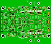
Thiago it looks great and I like also those curvy traces, but the Zobel network on the output...
The RC should preferably be connected before the output inductor, also please add some space between the output transistor source resistors so they don't become too cozy with each other, it can lead to some accidents! 😛

On Zobel PCB this is correct.
There are so many suggestions that I'm lost.

Thiago
Oh sorry, regarding the Zobel I admit I was looking too much only at the schematics which is differently drawn than the PCB, but now I see your PCB have it correct. 🙁
Have a look at the picture in post 439 to see how this is practical.
In post #439 the board shows no parts in the way so no problem there....
Fab
....
One of the problems of a system using dual nfb paths is where to derive the take-off points. Normally this would be further towards the output...

Hello Thimios.
Yes, the top is the GND and is connected to all the Cap and Power in the central point of GND IN + Cap feedback
Yes, the top is the GND and is connected to all the Cap and Power in the central point of GND IN + Cap feedback
Thiele's output network came in two forms.
R+C first followed by R//L to the load, or
R||L first to the R+C
Leach adopted this second alternative.
Cherry did a short article explaining that the two Thiele Networks were at opposite ends of a continuum. All there others being variations ranging between those extremes.
It is my opinion that the Zobel R+C has a stabilising effect on the very high frequency behaviour of the amplifier. This would be lost if the L portion moves the Zobel too far away from the output stage.
If one adopts the second alternative I think it is very important to keep the loop areas and thus inductance down by keeping all the connections back to the output stage VERY SHORT.
I was a little uneasy about that - the spacing of the paired FET's is also very close on the board in post 439. It seems marginable and a bit more breathing space would give more peace of mind. I have seen instances of the zobel following the coil - the Leach Low TIM amplifiers for instance.
One of the problems of a system using dual nfb paths is where to derive the take-off points. Normally this would be further towards the output - I would settle for how it is - in the circumstances of FET outputs and layout difficulties with two paths, changing this could be less helpful.
Hi mjona and sorry for a late reply, I didn't have a PDF reader available so I couldn't go back revisiting Leach's amp schematics as I wanted before replying back to you, but here's my take.
Leach uses a nested feedback concocted together with some lead-lag stuff used to improve the transient response, further on I noticed from a picture of the PCB outfitted with the components it seems like he uses wire wound resistors at the output transistors, these resistors are inductive and should be avoided at all costs! He even uses a plain capacitor between GND and chassis ground without a resistor in series, additionally there are a few other questions unanswered too, what I mean is, there are simply just too many variables and as such I think it is a rabbit hole I don't feel too compelled diving into regarding his choice of location of the RC Zobel, so I will leave it at that.
I still think he put the RC in the wrong place.
Back to the CFH7.
Regarding the OPS transistors and resistors, yes indeed, at least in our mind it feels more right to leave a bit of lebensraum for them, however, the vertical FET's such as the IRF parts used in this build have a positive Tempco and there is actually a sensible benefit to keep them thermally close to each other in order to improve thermal tracking and avoiding thermal runaway for any individual transistor.
One should just make sure to choose a heat sink with an enough thick base plate in order to avoid a local hotspot while at the same time having enough capacity to carry away the excessive heat.
To place vertical FET's close to each other has been done before and is a proven technique, on the other hand transistors with negative Tempco can be placed more sparsely.
Thiele's output network came in two forms.
R+C first followed by R//L to the load, or
R||L first to the R+C
Leach adopted this second alternative.
:
If one adopts the second alternative I think it is very important to keep the loop areas and thus inductance down by keeping all the connections back to the output stage VERY SHORT.
I would agree with all of what is said, but even if we put the "R||L first to the R+C " components in the vicinity of the OPS, how close are they electrically, and in particular the RC components (which Leach chose to put at the binding posts) to the OPS?
I think if we roll out the wire used in the output coil we would get closer to the answer and that isn't very short at all and any additional wire length would just improve the coil by its own resistivity and inductivity isolating even further capacitive effects of the loudspeaker cables, but I would still be keen on an explanation in case of I missed something, though I would rather believe with regards to the level of knowledge you have demonstrated in many posts that this was rather a temporary blunder which can happen even to the best of humans, after all it's Christmas.
To everyone, have a good continue on the Christmas holiday!


Hi mjona and sorry for a late reply, I didn't have a PDF reader available so I couldn't go back revisiting Leach's amp schematics as I wanted before replying back to you, but here's my take.
Leach uses a nested feedback concocted together with some lead-lag stuff used to improve the transient response, further on I noticed from a picture of the PCB outfitted with the components it seems like he uses wire wound resistors at the output transistors, these resistors are inductive and should be avoided at all costs! He even uses a plain capacitor between GND and chassis ground without a resistor in series, additionally there are a few other questions unanswered too, what I mean is, there are simply just too many variables and as such I think it is a rabbit hole I don't feel too compelled diving into regarding his choice of location of the RC Zobel, so I will leave it at that.
I still think he put the RC in the wrong place.
Back to the CFH7.
Regarding the OPS transistors and resistors, yes indeed, at least in our mind it feels more right to leave a bit of lebensraum for them, however, the vertical FET's such as the IRF parts used in this build have a positive Tempco and there is actually a sensible benefit to keep them thermally close to each other in order to improve thermal tracking and avoiding thermal runaway for any individual transistor.
One should just make sure to choose a heat sink with an enough thick base plate in order to avoid a local hotspot while at the same time having enough capacity to carry away the excessive heat.
To place vertical FET's close to each other has been done before and is a proven technique, on the other hand transistors with negative Tempco can be placed more sparsely.
I would agree with all of what is said, but even if we put the "R||L first to the R+C " components in the vicinity of the OPS, how close are they electrically, and in particular the RC components (which Leach chose to put at the binding posts) to the OPS?
I think if we roll out the wire used in the output coil we would get closer to the answer and that isn't very short at all and any additional wire length would just improve the coil by its own resistivity and inductivity isolating even further capacitive effects of the loudspeaker cables, but I would still be keen on an explanation in case of I missed something, though I would rather believe with regards to the level of knowledge you have demonstrated in many posts that this was rather a temporary blunder which can happen even to the best of humans, after all it's Christmas.
To everyone, have a good continue on the Christmas holiday!
I am off on holiday to the coast for a week. The inductive emitter resistor is to be avoided in bipolar designs. I understand a small amount of inductance in wire-wound types mitigates to a small extent with FET outputs. It would have the effect of providing more local source feedback at the frequencies where care is needed to ensure the high frequency capabilities can make FET's hairy.
Thiele gave two versions....................... regarding his choice of location of the RC Zobel, so I will leave it at that.
I still think he put the RC in the wrong place.
.............................
I would agree with all of what is said, but even if we put the "R||L first to the R+C " components in the vicinity of the OPS, how close are they electrically, and in particular the RC components (which Leach chose to put at the binding posts) to the OPS?
I think if we roll out the wire used in the output coil we would get closer to the answer and that isn't very short at all and any additional wire length would just improve the coil by its own resistivity and inductivity isolating even further capacitive effects of the loudspeaker cables, but I would still be keen on an explanation in case of I missed something, ............
Leach adopted the second version.
But I think your analysis misses the resistor in parallel to the inductor.
Option two:
Going from the output node to the resistor, thence to the R+C and back to the local decoupling, can be a short route.
Compare to the first option:
Going from the output node to the R+C and back to the local decoupling can be a short route.
The extra route length between the first and second options of the Thiele Network is just the length of the resistor. This could be as little as 10mm.
The extra length is NOT the length of the unwound inductor.
Admittedly the second is not quite as short as option one.
Last edited:
As far as the Leach amp is concerned there are more hf attenuation components in the output signal thus it is routing these to earth sooner than is the case for the speaker feedback return route. There is quite a lot of inductance in speaker cable that feeds into the zobel for the return signal.
Re source resistor inductance and FET outputs hf switching generates beyond the spectrum ability of bjt's. More loop gain arises from this characteristic but in the last respect it can be too much of a good thing. BJT's struggle at hf which is not enough of a good thing - inductance in emitter resistors is counter productive since it will reduce loop gain at hf.
There is another stability output network due to N.Thiele that is said to guarantee stability. Silicon Chip magazine projects have used this for 20 years.
A point to make about a zobel network is this relies on the performance of the capacitor at hf. In the Leach amplifier this is sandwiched between two inductors - the one inside the amplifier and an albeit less perfect one the speaker cable. Just how good are the sort of capacitors necessary in a high power wide bandwith amplifier?
Thiele's output network came in two forms. (1st option) R+C first followed by R//L to the load, or (2nd option) R||L first to the R+C Leach adopted this second alternative.... .....If one adopts the second alternative I think it is very important to keep the loop areas and thus inductance down by keeping all the connections back to the output stage VERY SHORT.
But I think your analysis misses the resistor in parallel to the inductor.... .....The extra route length between the first and second options of the Thiele Network is just the length of the resistor. This could be as little as 10mm....
Indeed, I "forgot" to mention the so very important 10 Ohm resistor in parallel with the 4,7 uH output coil which obviously dramatically alter the game in favor for the omnipotent and omniscient Oracle by a whopping "10mm", what ever that is worth in RL equivalency on a PCB for audio applications!
All the "very short loop" paranoia talk when dealing with the 2nd option R||L+R+C setup, ie. secondary side RC location, seems somewhat exaggerated when the RL itself mimics a very long low capacitive cable, and no, we don't measure RL components electrical value in millimeters.
---
Mjona, I believe you have made some good observations analyzing the Leach amp, I for one am at this point in time quite rusty as it is several years ago I read through his material, I ought to revisit and read through it again, I just recall it, it was quite an entertaining audio-intellectual reading. You have a point regarding inductive resistors on BJT OPS, but then again I wonder why an RC on the primary side of the output coil would cause it oscillate, Leach mentioned GND currents, but that makes me think something isn't decoupled correctly? The amp is complex and maybe he didn't want to sacrifice speed for better stability as I guess this was TIM inspired amp from around the days of Matti Otalas work on TIM? Too many questions, I admit that it's an interesting amp to discuss though, but I better try re-read his work and try understand it better first.
Cheers
Perhaps Thimios can add Thiele network and see if measuremts get even better? Why is it none of the class A Pass amps have a Thiele or Zobel network?
Is the Leach amp a good performer? That is, does it 'sound good'?
HD
Me and some friends built Leach and for me there is nothing special, despite being stable and playing well.
My favorite list of amplifiers today is.
-AX11
-QUASI
-ACA turbo
My list has already been built.
DOZ, Leach, JLH 69, Gainclone lm3886 and lm1875, AX11, A33, PEECEEBEE, Myref. Mauro Penasa, Quasi, FH9, ACA, P3A.
Thiago
The Leach Low TIM 1st revision is an amplifier I built and lived with for a long time. A friend had a later version I thought was better. A limiting factor as far as subjective results go was the fact I had unspectacular loudspeakers. That said it never got much more than warm when played at high volume.
The zobel arrangement and the bias system for the output stage worked against crossover distortion and instability. A measure of that can endow lesser amplifiers with an impression of more excitement. It can take a while to ween oneself away from this and get closer to neutrality.
If I was to do a rebuild I would look more closely about issues like fuses in supply rails earthing routing of wire low impedance capacitors to give it a boost.
An example of Thiele's ouput network is a series coil of 6uH//8R(1watt) with cap to earth at speaker end of 150nF MKT 400 volt. For high power use at frequencies of 10kHz the 8R resistor should be uprated to 5 watt.
In this the coil takes some heat out of equation as far as the 150n cap is concerned.
I have seen MOSFET amplifiers where the resistor in the Zobel has burned out.
I see these alternatives as a belt and braces option for Miller capacitor compensation which is done in the forward signal path. Steps are necessary to guard the back door to the inverting input,
Hi guys, thanks a lot for this fantastic work Sorry for just skimming the whole thread, perhaps I overlooked...
Please what is the lowest supply voltage? Can the amp be made less powerfull?
Can the gain be lowered to accomodate higher input voltage? I am thinking of volume control from one half of balanced studio-level with subsequent voltage divider - I want to keep the voltage as high as possible due to noise.
Thanks a lot.
- Home
- Amplifiers
- Solid State
- CFH7 Amp