

Thiago,
A very pretty pcb, you have a distinctive trademark, I love it!
I can see no criticism, but I have not checked all the nets. Certainly looks lovely.
Hugh
A very pretty pcb, you have a distinctive trademark, I love it!
I can see no criticism, but I have not checked all the nets. Certainly looks lovely.
Hugh
Beautiful layout.
I don't see how the signal Gnd is tied to the Power Gnd ? Maybe I checked too quickly.
BR,
Eric
I don't see how the signal Gnd is tied to the Power Gnd ? Maybe I checked too quickly.
BR,
Eric
Thanks Hugh, it's always nice to know you like something I did.
Hi Eric, look again, two ground connections or a jumper can be made. thank you
Hi Eric, look again, two ground connections or a jumper can be made. thank you
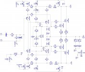
The larger a capacitor is physically, the more it is at risk of having some reaction with electromagnetic fields generated by the output stage and power supply. The 10uF capacitor in the non inverting signal input and the two 2200uF 6.3 volt connected to the two inverting signal inputs are cases in point.
The latter electrolytics should be closer together. Making the input layout more compact could be helped if a normal single nfb decoupling arm was used.
That would involve removing the 47R resistors in series with the 15K supply resistors and connecting the latter directly to the emitters of BC560 and BC550.
From these points ( in opposite parallel) to a common connection at the opposite end the 2200uF 6.3volt capacitors would form single a.c. summing junction then taken to earth via a single 47R resistor.
Bypassing a electrolytic capacitors with a plastic type entails some risk of a interaction - this due to different resonance characteristics, resulting in the generation of a spurious voltage. You are still using this on the supply rails of your revised layout.
The emitters of BC560 and BC550 as well as being inverting signal inputs are connected to the supply rails. Negative feedback does not act as a guard to clean up when the trouble comes in with the guard.
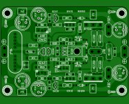
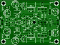
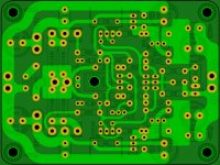
First layout attempt.
Any criticism is welcome.
Thiago
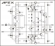
Beautiful layout as usual Thiago. Why are you specifying different VAS than KSA/KSC?
Does this circuit implement suggestions by Thimios to fix PSRR issue?
CFH....new generation
As the title say.......at first without cpx
As the title say.......at first without cpx
Attachments

Last edited:
Beautiful layout as usual Thiago. Why are you specifying different VAS than KSA/KSC?
Does this circuit implement suggestions by Thimios to fix PSRR issue?
Hi XRK.
I just have many BF469-470 so I use it, but I've already moved to KSC-KSA. Many low COB high FT TO220 can be used.
Thiago
The larger a capacitor is physically, the more it is at risk of having some reaction with electromagnetic fields generated by the output stage and power supply. The 10uF capacitor in the non inverting signal input and the two 2200uF 6.3 volt connected to the two inverting signal inputs are cases in point.
The latter electrolytics should be closer together. Making the input layout more compact could be helped if a normal single nfb decoupling arm was used.
That would involve removing the 47R resistors in series with the 15K supply resistors and connecting the latter directly to the emitters of BC560 and BC550.
From these points ( in opposite parallel) to a common connection at the opposite end the 2200uF 6.3volt capacitors would form single a.c. summing junction then taken to earth via a single 47R resistor.
Bypassing a electrolytic capacitors with a plastic type entails some risk of a interaction - this due to different resonance characteristics, resulting in the generation of a spurious voltage. You are still using this on the supply rails of your revised layout.
The emitters of BC560 and BC550 as well as being inverting signal inputs are connected to the supply rails. Negative feedback does not act as a guard to clean up when the trouble comes in with the guard.
Thank you for that. I thought the big movie capacitor would be good here. Should I switch to a 10uF electrolytic?
Thiago
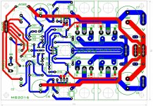
First layout attempt.
Any criticism is welcome.
Thiago
You can use 2,2uF instead 10uF input cap and no need to use MUR160 diode...
Attachments
You might want to rethink the value of C14 and C16. It was 2,200uF earlier and now the last schematic shows 220uF. You can see that the PSRR drops quite dramatically with 2,200uF. However you may want to check how audible the effect it. The Top red curve is 220uF and the bottom blue curve is 2,200uF. This is the PSRR for the positive rail. The negative rail is identical.
Something odd in my Spice program ( B2spice). 10 ohms with 220uF and 2200uF plots as shown. But higher values like 15 ohms and more degrades the PSRR seriously. Looks like it interferes with the previous stages ! Check it on LTspice. I can't do that now.
Something odd in my Spice program ( B2spice). 10 ohms with 220uF and 2200uF plots as shown. But higher values like 15 ohms and more degrades the PSRR seriously. Looks like it interferes with the previous stages ! Check it on LTspice. I can't do that now.
Attachments
Last edited:
You might want to rethink the value of C14 and C16. It was 2,200uF earlier and now the last schematic shows 220uF. You can see that the PSRR drops quite dramatically with 2,200uF. However you may want to check how audible the effect it. The Top red curve is 220uF and the bottom blue curve is 2,200uF. This is the PSRR for the positive rail. The negative rail is identical.
Something odd in my Spice program ( B2spice). 10 ohms with 220uF and 2200uF plots as shown. But higher values like 15 ohms and more degrades the PSRR seriously. Looks like it interferes with the previous stages ! Check it on LTspice. I can't do that now.
What is PSRR with BC546/556 and 4k7/22uF cap Mx I wonder?
I'm guessing you are referring to the circuit in post 819 ( 4.7K ).
I added 4.7K as shown and put the 22uF ( and later 220uF) from the junction of 15 k and 4.7K to ground. The 10 ohms and diode and the 220uF shown there were removed.
The black curve on top is the original with 2200uF and 10 ohms in the last circuit shown in post 867.
The next blue curve is with 4.7k and 22uF and red curve below is 220uF and 4.7K .
Attachments


Idefixes,do not draw a new PCB keeping the offset trimmer in that position.As the title say.......at first without cpx
This is a very bad idea . Look at thiago PCB.
Two trimmers,for offset and VAS current adjustment.😉
Idefixes,do not draw a new PCB keeping the offset trimmer in that position.
This is a very bad idea . Look at thiago PCB.
Two trimmers,for offset and VAS current adjustment.😉
Ok I see what you mean.....
Marc
Thiago,why one pair of output fet?
Please draw for two pairs,if someone need one only,just keep the other unpopulated.😉
Please draw for two pairs,if someone need one only,just keep the other unpopulated.😉
Thiago,why one pair of output fet?
Please draw for two pairs,if someone need one only,just keep the other unpopulated.😉
Good idea 😉
I changed the 22uF to 100uF. It lies between the 22uF and 220uF and gives 28dB reduction at 100Hz , your supply ripple frequency. Check it out. It's the black curve between the 22uF and 220uF curves.
The cap Mx is impressive and only makes sense to include it in the next build.
So this is without cap Mx? -115dB to -120dB PSRR at line frequency is quite the bonus and matched Thimios measured -115dBsignal amplitude at line frequency (50Hz and 100Hz) without cap Mx. Not bad at all.
Last edited:
- Home
- Amplifiers
- Solid State
- CFH7 Amp