I think you misunderstand my post, I was not clear, sorry.
My main point was that the decrease in output resistance that VZaichenko proposes as an explanation is extremely unlikely because he did not consider the effect of overall feedback,
The actual decrease in output resistance is likely to be in the micro-ohms and therefore utterly undetectable.
The effect of the altered Rb on the previous sections only makes any difference even smaller because the effect of the altered Rb reflected to the earlier sections partly cancels out the effect of the Rb reflected to the load.
So it does not seem likely to be output impedance that causes an audible difference, if one exists.
What was your test size and protocol?
Properly unbiased?
Statistically reliable?
Best wishes
David
GNFB influence on Zo - agree. Depends on OLG, but I agree - portion, related to the base stoppers is rather small.
On the other hand - there are at least 2 other effects, related to the base stoppers:
1) Equivalent beta decrease (as stopper value increases);
2) Optimal bias shift - with stopper in place it is lower, than the one for "no stopper" configuration.
So, comparison exercise requires re-biasing, to keep crossover distortion at minimum.
Anyway, I agree with Richard - my experience also shows that the amp sounds better (more solid, "controlled" sound) after removing the base stoppers ftom the output pairs (experimented with 1 and 2 pairs). Assuming, OPS remains stable at all times, of course.
I don't know the right reason for that, just trying to "think aloud" 🙂
P.S. There must be a reason for the fact, that practical maximum value of the OPS base stopper is somewhat 4.7 Ohm, though the optimal one is around 2.2 Ohm. I mean, some 20 Ohm will make the output transistor very "ineffective". Distortuon will increase for sure. Even NFB will not "save" it. So - the less is the better. Ideas? 😉
Inductances ?Any suggestions on how I might reliably reduce the output stoppers...?
Hi again,
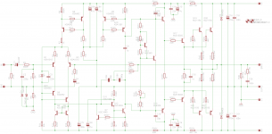
Attached is the design I'm working on. Its a bit of a melting pot of ideas from various projects. The OPS is essentially OStripper's Slewmonster. Any suggestions on how I might reliably reduce the output stoppers from 4R7 to 2R2?
My opinion - just switch to 2R2, check if the amp is still stable (I hope so) and re-bias.
As a fine-tuning exercise, you can measure THD, adjusting the OPS quiescent current slightly up and slightly down, finding the best value with lowest distortion.
Cheers,
Valery
... Depends on OLG...
No, it depends on LG not OLG.
It is easy to confuse such similar terms so I prefer to use Return Ratio and Forward Transfer Function.
How are these named in Russian?
Actually it really depends on the so-called Sensitivity which Bode showed is not exactly the same as the Return Ratio.
Luckily they are practically identical for an audio amp at low frequency, because I still need to understand better the difference myself.
Anyone have any links for this? The only real discussion I have read was Cherry, as usual.
Best wishes
David
LG = OLG - CLG Right?
Assuming CLG is constant (set by GNFB), OLG and LG are directly inter-connected.
Do I understend it right? 🙂
Any suggestions on how I might reliably reduce the output stoppers from 4R7 to 2R2?
I would suggest a ground and power plane layout with RC snubbers directly at the power transistors. Of course where exactly the snubbers should go is a difficult question. You could put a snubber between any two pins, it just depends on exactly where the problem is...
Plane layout is used to decrease inductance. This mostly just shifts the problem frequency higher, with shielding and magnetic containment as side-benefits. The actual advantage to this is that you can use a smaller snubber, which will be less likely to fry during oscillation or to cause distortion by loading the drivers.
If parasitics are completely understood and accounted for, and the amplifier is designed not to encourage local oscillation, then I think it's worth trying to eliminate base stoppers, because it will allow you to reduce the stability compensation of the amplifier.
Of course this is highly experimental. Maybe you don't want to fiddle with it for weeks to get this right.
On the other hand - there are at least 2 other effects, related to the base stoppers:
1) Equivalent beta decrease (as stopper value increases);
2) Optimal bias shift - with stopper in place it is lower, than the one for "no stopper" configuration.
1) No. Beta is defined as Beta=A/(1-A) where A=Ic/Ie and is always <1, due to the unavoidable charge carriers recombination in the base. The base stopper has no bearing with this mechanism. The equivalent transconductance, yes, it is affected by the base stopper.
2) The optimal bias shift, yes, the base stopper reflects in the emitter as Rb/Beta, so a 5ohm base stopper contributes as an extra 0.1ohm in the emitter (considering Beta=50). However, that's not the whole story. Because Beta also depends on temperature, the base stopper worsens the temperature stability of the EF, by adding a positive feedback mechanism. That's because the base stopper contribution to the emitter resistor is decreasing with temperature (since Beta increases). This is in particular bad when having multiple devices in parallel, since it also stimulates current hogging.
Also because it contributes to the emitter resistor, increasing the base stopper increases the distortions. However, since decreasing the emitter resistor decreases distortions but makes the optimum bias sharper, you may want, as usual, to pick your poison.
Anyways, the base stopper should be as low as possible to provide stability. I cringe when I see 10ohm base stoppers, like in some successful commercial designs, and always wondered if the marketing line of "hand matched devices" was not required precisely because of that base stopper design decision. OTOH, if an EF is not stable without 10 ohm base stoppers, then there's certainly something very wrong with that design.
100% correct
Cheers
S
Indeed, the base resistor has a different effect than the emitter resistor .. especially as it affects stability.1) No. Beta is defined as Beta=A/(1-A) where A=Ic/Ie and is always <1, due to the unavoidable charge carriers recombination in the base. The base stopper has no bearing with this mechanism. The equivalent transconductance, yes, it is affected by the base stopper.
2) The optimal bias shift, yes, the base stopper reflects in the emitter as Rb/Beta, so a 5ohm base stopper contributes as an extra 0.1ohm in the emitter (considering Beta=50). However, that's not the whole story. Because Beta also depends on temperature, the base stopper worsens the temperature stability of the EF, by adding a positive feedback mechanism. That's because the base stopper contribution to the emitter resistor is decreasing with temperature (since Beta increases). This is in particular bad when having multiple devices in parallel, since it also stimulates current hogging.
Also because it contributes to the emitter resistor, increasing the base stopper increases the distortions. However, since decreasing the emitter resistor decreases distortions but makes the optimum bias sharper, you may want, as usual, to pick your poison.
Anyways, the base stopper should be as low as possible to provide stability. I cringe when I see 10ohm base stoppers, like in some successful commercial designs, and always wondered if the marketing line of "hand matched devices" was not required precisely because of that base stopper design decision. OTOH, if an EF is not stable without 10 ohm base stoppers, then there's certainly something very wrong with that design.
Would you like to explain the 'real life' behaviour in http://www.diyaudio.com/forums/solid-state/234408-stability-analysis-ef-output-stages-2.html#post3461363?
This isn't a 'design'. It's just a single stage EF driving 8R. It's unstable.
You can confirm this 'real life' behaviour with any type of BJT power devices.
This isn't a 'design'. It's just a single stage EF driving 8R. It's unstable.
You can confirm this 'real life' behaviour with any type of BJT power devices.
EF stability analysis is a non trivial topic, and by far exceeds the scope and technical capabilities (equations, graphs, etc...) of a public forum (and besides, it would be off topic). It is though addressed in any decent electronics book, sorry if there aren't any around, buried in the beach sand.
In my opinion, in your particular case, the instabilities are due to a combination of high Ft devices with a questionable layout or wiring. The stabilized power supplies may also play a role, as they usually have an inductive output impedance. No, such a simple stage will likely oscillate only with high Ft devices (yours are 15MHz). With low Ft devices it will be, most likely, stable.
I have settled on 3.3 ~4.7 ohms for the base stopper and 0.33 ohms Re.
I am getting very good results. Output EF3 stages are stable, bias is also stable.
I don't think it's worth pushing the the base stopper too low in an EF3 - especially a big amp because a failure can be expensive. Worse, unstable SMPS sound crap.
Thee are many things to agonize over in high end audio. The base stopper in my view is quite low down on the list - thousands ( millions?)! of amplifiers have been built with base stoppers in the 2.2 to 4.7 ohm range without incident.
Don't worry, be happy, and just build the damn thing.
Indeed. In the thread that Richard linked I recommended Ovidiu's site because it looked impressive. A more careful look has left me unsure, the analysis is not clear to me.EF stability analysis is a non trivial topic...
...addressed in any decent electronics book, sorry if there aren't any around, buried in the beach sand.
Luckily, I am close to several excellent libraries😉 so which books do you recommend?
Dennis Feucht's work also initially looked impressive but a close examination has left me a little unconvinced here too.
Sometimes explanations just don't fit one's view point, so different perspectives help. Anyone else have a favourite?
I expect Andrew will not mind, or just post in that EF stability thread.
Best wishes
David
1) No. Beta is defined as Beta=A/(1-A) where A=Ic/Ie and is always <1, due to the unavoidable charge carriers recombination in the base. The base stopper has no bearing with this mechanism. The equivalent transconductance, yes, it is affected by the base stopper.
2) The optimal bias shift, yes, the base stopper reflects in the emitter as Rb/Beta, so a 5ohm base stopper contributes as an extra 0.1ohm in the emitter (considering Beta=50). However, that's not the whole story. Because Beta also depends on temperature, the base stopper worsens the temperature stability of the EF, by adding a positive feedback mechanism. That's because the base stopper contribution to the emitter resistor is decreasing with temperature (since Beta increases). This is in particular bad when having multiple devices in parallel, since it also stimulates current hogging.
Also because it contributes to the emitter resistor, increasing the base stopper increases the distortions. However, since decreasing the emitter resistor decreases distortions but makes the optimum bias sharper, you may want, as usual, to pick your poison.
Anyways, the base stopper should be as low as possible to provide stability. I cringe when I see 10ohm base stoppers, like in some successful commercial designs, and always wondered if the marketing line of "hand matched devices" was not required precisely because of that base stopper design decision. OTOH, if an EF is not stable without 10 ohm base stoppers, then there's certainly something very wrong with that design.
Well put.
Yes, one of those designs has 9 output pairs.
Cheers,
Bob
Anyway, I agree with Richard - my experience also shows that the amp sounds better (more solid, "controlled" sound) after removing the base stoppers from the output pairs (experimented with 1 and 2 pairs). Assuming, OPS remains stable at all times, of course.
It may come as a surprise to some that this affect has been heard for a very long time..... not something I heard myself the until doing the Rb change, recently..... same sound effect as described by you and others. So, I dont think it is a write-off as coincidence or mass delusion or a placebo affect.
So far, the take-away I get here is lowered distortion is the audible affect I heard. As was also noted, idle bias would need and was retuned for lowest thd. So, we dont have a single change to say what caused what. Again, the distortion levels were not high to begin with.... so I am now leaning more and more towards the lower limits of thd or harmonic level which can be heard is at lower levels than has been academically established in the past. Possible, in part, due to wide bandwidth, low distortion speaker systems.
THx-RNMarsh
Last edited:
In EVERY SINGLE CASE when my Blind Listening Test Panel observed these 'dramatic differences' in the bass, it was cos one of the amps was marginally unstable on real speaker loads.It may come as a surprise to some that this affect has been heard for a very long time..... not something I heard myself the until doing the Rb change, recently..... same sound effect as described by you and others. So, I dont think it is a write-off as coincidence or mass delusion or a placebo affect.
So far, the take-away I get here is lowered distortion is the audible affect I heard. As was also noted, idle bias would need and was retuned for lowest thd. So, we dont have a single change to say what caused what. Again, the distortion levels were not high to begin with.... so I am now leaning more and more towards the lower limits of thd or harmonic level which can be heard is at lower levels than has been academically established in the past.
At one time, I would have claimed ALL Golden Pinnae amps had wonky stability. Wouldn't be surprised if it wasn't still true 🙂
It Could be true for this one as well.... but it wasnt. I am well vested in test equipment to see such things from DC to near Light.
If anything the stability would be potentially worse when lowering the Rb and thus would sound worse when 'acting out' and not better. [it wasnt one amp design vs another.]
Now what?
THx-RNMarsh
If anything the stability would be potentially worse when lowering the Rb and thus would sound worse when 'acting out' and not better. [it wasnt one amp design vs another.]
Now what?
THx-RNMarsh
Last edited:
I have settled on 3.3 ~4.7 ohms for the base stopper and 0.33 ohms Re.
I am getting very good results. Output EF3 stages are stable, bias is also stable.
I don't think it's worth pushing the the base stopper too low in an EF3 - especially a big amp because a failure can be expensive. Worse, unstable SMPS sound crap.
Thee are many things to agonize over in high end audio. The base stopper in my view is quite low down on the list - thousands ( millions?)! of amplifiers have been built with base stoppers in the 2.2 to 4.7 ohm range without incident.
Don't worry, be happy, and just build the damn thing.
I used 2.2 ohm for the base stopper and 0.16 ohm for the Re in my EF3 TT amp, schematic is here http://www.diyaudio.com/forums/solid-state/182554-thermaltrak-tmc-amp-10.html#post3031504.
In some other amps I used 1.8 ohm for the base stopper, all that with no stability problems, PCB layout plays important role here.
😎🙂
THx-RNMarsh
In all Blind Listening Tests, you first establish there is a reliable difference.It Could be true for this one as well.... but it wasnt. I am well vested in test equipment to see such things from DC to near Light.
If anything the stability would be potentially worse when lowering the Rb and thus would sound worse when 'acting out' and not better. [it wasnt one amp design vs another.]
THEN you ask for Preferences but ONLY from those who have a reliable preference.
How do YOU test for stability Mr. Marsh?
And don't ignore the possibility that even true golden pinnae (like my DBLT panel) may sometimes prefer a 'distorted' signal.
The difference from them and the Golden Pinnae brigade is that they will return consistent results from test to test. Unlike the pseudo Golden Pinnae brigade who will hear 'chalk & cheese' even if all presentations are of the same item.
Last edited:
- Home
- Amplifiers
- Solid State
- CFA Topology Audio Amplifiers