I do not wish to go off on a tangent about listening testing here. You may take the position that there was no change in sound. But, if you took the position that there was an audible change (for the better), what would be the explanation? So far it seems like lowered distortion from the theory of circuits and Rb's role.
Another possibility is that the OPS was current starved into low Z speaker -- especially if the Z went much lower than 4-8 Ohms (and there are two bass drivers in parallel in each speaker cabinet... such extraneous details are important to a complete analysis). Thus, the hint about increased Ib.Any more thoughts about this other possibility?
THx-RNMarsh
I don't know how you conduct your DBLTs so I can't comment but DBLTs come out with more than the NULL results that the Golden Pinnae brigade seem to dislike so much.I do not wish to go off on a tangent about listening testing here. You may take the position that there was no change in sound. But, if you took the position that there was an audible change (for the better), what would be the explanation? So far it seems like lowered distortion from the theory of circuits and Rb's role.
Another possibility is that the OPS was current starved into low Z speaker -- especially if the Z went much lower than 4-8 Ohms (and there are two bass drivers in parallel in each speaker cabinet... such extraneous details are important to a complete analysis). Thus, the hint about increased Ib.Any more thoughts about this other possibility?
What I'm saying is that IF you heard a change in sound, a possible explanation is marginal instability. It's by far the biggest cause of audible differences in amps in my DBLTs .. IF the amp isn't overloaded.
Hence my question about how YOU test stability.
The lowered distortion and current starvation explanations are ones you can easily test with your supa dupa gear. In any competent amp, they are unlikely to be the problem. That's not to say incompetent Golden Pinnae stuff won't have problems.
And I'm real suspicious of any amp where reduced Rb on the outputs (with optimum rebiasing bla bla) results in significantly less THD. 😱
Changing Rb has some similar effect as Re but not exactly .. especially with stability.
Last edited:
I sim simple amp with double emitter follower output. First picture, I use 100 Ohm for Rb on driver and 10 Ohm for Rb on final. Second picture, I use 22 Ohm for Rb on driver and 2.2 Ohm for Rb on final.
Less Rb, less distortion but sometime I get peaky frequency response.
Less Rb, less distortion but sometime I get peaky frequency response.
Attachments
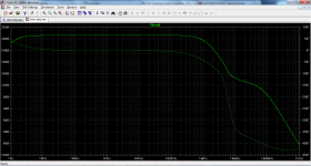
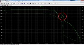
You have some other problem Bimo. Might be the 100 ohm is introducing a pole. You can't put plots up like this without including some detail unfortunately.
You have some other problem Bimo. Might be the 100 ohm is introducing a pole. You can't put plots up like this without including some detail unfortunately.
It is not about CFA, but simple VFA. If you don't mind, I can upload the sim file.
Dennis Feucht's work also initially looked impressive but a close examination has left me a little unconvinced here too.
Not sure why Feucht's work didn't cut it for you (looks pretty clear and complete to me) but anyways, here are a few more resources I was able to grab quickly:
Emitter Follower Stability
T. Moto-Oka, H. Guckel, T. A. Murrell, University of Illinois at Urbana-Champaign. Graduate College. Digital Computer Laboratory (1963)
https://archive.org/stream/emitterfollowers134moto#page/n31/mode/2up
Wideband Amplifier Design
Allen L. Hollister(2007)
ch. 2.6 (uses the Routh-Hurwitz stability criteria)
An Investigation of the Stability of a Transistor Emitter-follower Circuit
Ivars George Akmenkalns (1961)
Graphical Emitter Follower Stability Analysis
Frederick Andrew Perner (1970)
Emitter Follower Stability
T. Moto-Oka, H. Guckel, T. A. Murrell, University of Illinois at Urbana-Champaign. Graduate College. Digital Computer Laboratory (1963)
https://archive.org/stream/emitterfollowers134moto#page/n31/mode/2up
I was born on the 2-nd day after it was published 🙂
Waly, thank you for the list - 2 publications are new to me...
still seems like lower distortion is being heard. Now I changed the Re to .15. And, rebias. Together with lower Re and lower Rb and rebias, the sound is best to date. Lower is better all around. The change in THD was not great but it was lower.
Look I'm an old man now and if I can hear the change in sound qaulity, it must be larger to younger ears. its now about .001% THD at 1Khz and at 1- 30W into R = 8.
It really isnt too puzzling .. every time I get THD well under my hearing detection/threshold, it sounds best. Duh.
THx-RNMarsh
Look I'm an old man now and if I can hear the change in sound qaulity, it must be larger to younger ears. its now about .001% THD at 1Khz and at 1- 30W into R = 8.
It really isnt too puzzling .. every time I get THD well under my hearing detection/threshold, it sounds best. Duh.
THx-RNMarsh
Last edited:
I just thought of something..... the circuits to current limit/SOA design. And, I did not reset them when Re was lowered.... so would allow a lot more current. maybe thats why the symptoms seemed like current limited ??
BTW - in doing this change part biasing and T&M and then listen -- I smoked an output device a few times. Destructive testing to find if the limit to improved sound was possible with these R changes or if a minimum/null in the changes... I only found the sound (and distortion) less distorted until it gave up..... heat- excessive current- whatever.
Think I'll go to more robust and higher current OPS devices and try this again. [its a 250W/8 amp, as it is.]
But, I did answere by curiousity about those changes and they make any differnce in the sound. Just checking on the 'why' part with you guys.
THx-RNMarsh
Last edited:
Don't know. When i was a young sound engineer, i wondered how mervelous were some drums, mixed by some old sound engineers around. Specially how natural was their cymbals. While i was trying so hard, with my treble correctors, for an unsatisfying result on my point of view ;-)Look I'm an old man now and if I can hear the change in sound qaulity, it must be larger to younger ears.
And i don't believe you're such an old man neither;-)
Don't know. When i was a young sound engineer, i wondered how mervelous were some drums, mixed by some old sound engineers around. Specially how natural was their cymbals. While i was trying so hard, with my treble correctors, for an unsatisfying result on my point of view ;-)
And i don't believe you're such an old man neither;-)
Never ever get old. I refuse. However, my body has other plans for me. Thats Ok... keep on moving. BTW -- Patti went back home to her husband after a month hanging with me and Lisa here in Asia. Now, i get an email from her telling me her arm is broken in two places. WTF ?
One thing I do know --- never make assumptions. 🙂
I also know that experience does seem to count quit a lot and adds a lot of pleasure to ones endeavours.
-Richard Marsh
Last edited:
1)
2) The optimal bias shift, yes, the base stopper reflects in the emitter as Rb/Beta, so a 5ohm base stopper contributes as an extra 0.1ohm in the emitter (considering Beta=50). However, that's not the whole story. Because Beta also depends on temperature, the base stopper worsens the temperature stability of the EF, by adding a positive feedback mechanism. That's because the base stopper contribution to the emitter resistor is decreasing with temperature (since Beta increases). This is in particular bad when having multiple devices in parallel, since it also stimulates current hogging.
.
BTW --- very 😎🙂 details and their explanation.
Thx-RM
With age , the ears become physically impaired .... but the mind interprets
what does come through, more thoroughly .
PS - at 20 , some could actually "sneak up" on me. Now , at 50 ... not
a chance.
OS
what does come through, more thoroughly .
PS - at 20 , some could actually "sneak up" on me. Now , at 50 ... not
a chance.
OS
One silly question, in this thread some ware (I think) it was said that the voltage across Re should be near 25mV for optimal bias, if one keeps lowering Re than the bias current will go up up and up ..., is that so and what would be a 'balpark' figure for bias in relation to Re?
One silly question, in this thread some ware (I think) it was said that the voltage across Re should be near 25mV for optimal bias, if one keeps lowering Re than the bias current will go up up and up ..., is that so and what would be a 'balpark' figure for bias in relation to Re?
A distortion optimum is always at kT/q=26mV across Re. However, it is not obvious what exactly Re is. In a nutshell, it's at least the physical emitter resistor, plus the internal parasitic Re of the device, plus the base stopper divided by Beta (and that applies exactly only if Beta is "large enough"). These components are making some to believe that in fact the optimum is at a much lower bias, which is not true.
As already mentioned, distortions are decreasing with Re (that is, as a result, at a larger bias current). Set aside the thermal and current hogging issues with very small Re's, the lower Re the more critical the bias value. That is, if you plot distortions vs. the bias current you will get, for small Re's, a sharp drop at the optimum bias, while for larger Re's, you will get a higher minimum at the optimum bias, but the curve will be much flattened. Therefore, except for some rather complex non-switching bias arrangements, it's not worth the risk to choose very small Re's.
Because of the involved trade offs, the definition of an opinion applies: they are like ...holes, everybody has one. My rule of thumb, based on my own limited experience, is that you can get along with .22ohm for 1-2 output pairs biased at 80-100mA each, 0.33 for 3-4 pairs biased at 70-80mA each and 0.47 for 5 and up biased at 60-70mA each, these arrangements also providing a decent thermal stability. Without matching the output pairs, of course. Over biasing is always better than under biasing, and that's not because of the THD, but because the spectra of the distortions are nastier (more high order distortions) for bias current starved output stages.
This agrees very much with what I find is optimum for my current amplifier, it uses 4 parallel devices using Re's of 500mOhm (maybe a bit high, I will do some experiments with 390 and 330mOhm) and is running a total bias of 300mA (75mA/device). Thanks for this information.
P.s. the 500mOhm was selected to get near the 25mV over Re while still being at a reasonable bias current (the amp runs on +-70V and a Re of 220mOhm would up the standby power dissipation to a (I think) non acceptable level). The 75mA (and not 45 to 50 as dictated by the 25mV) was selected by using ears 🙂 (attached to people).
Last edited:
Never ever get old. I refuse. However, my body has other plans for me. Thats Ok... keep on moving. BTW -- Patti went back home to her husband after a month hanging with me and Lisa here in Asia. Now, i get an email from her telling me her arm is broken in two places. WTF ?
One thing I do know --- never make assumptions. 🙂
I also know that experience does seem to count quit a lot and adds a lot of pleasure to ones endeavours.
-Richard Marsh
My Mom says age is just a number. She should know - she's 98.
In April I became a grandfather for the first time. What a pleasure!
Cheers,
Bob
In April I became a grandfather for the first time. What a pleasure!
Cheers,
Bob
Bob, congratulations!
Jan
What is the name of the free electron ?In April I became a grandfather for the first time. What a pleasure!
What is the name of the free electron ?
Jayden Cordell, born to my son Jon and his wife Amy.
Cheers,
Bob
- Home
- Amplifiers
- Solid State
- CFA Topology Audio Amplifiers