Well, when we can reduce them, ok, but when we cannot ?I prefer NOT to have to deal with parasitics.
I have always in a corner of my mind those two tips:
- Try to get each stage a little faster than the previous one.
- If there is some parasitic i cannot suppress, let-s try to use-it, 'judo' like.
Hi OS, is there a reason why you chose not to decouple the rails between the driver and pre-driver on your Slew-OPS? I.e. is it unconditionally stable without?
Also wondering whether the output base stoppers can be reduced from 4R7 to 2R2 and the driver stoppers from 22R to 10R without any ill effects. If not, would driver-pre-driver collector decoupling allow the base stoppers to be reduced in value, or does one have nothing to do with the other?
Design features will dictate whether base stoppers are needed or not and whether they can be decreased. The same goes for the decoupling. The design methods of one designer is not neccesarily the universal and only correct way of accomplishing a required result.
As I dont see anyone give you a straight answer, I had a quick look at LTT4 amp. See C19. Thats the reason the LTT4 can probably get away whithout base stoppers. On this particular topology thats the way I would design it as well although I would include 2.2 ohm base stoppers on the outputs. There are some speakers on the market that make for nasty loads and its better safe.
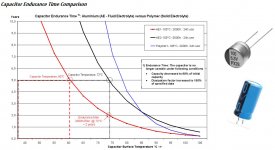
Electrolytic capacitors endurance time comparison
Somewhat off-topic - not directly related to CFA, however I don't think it deserves a separate thread and most of the people who may be interested read this thread anyway.
I've found this graph in a technical paper for the industrial motherboard from a well-known manufacturer.
Interesting point - though at the rated temperature (105C) 2000h polymer caps are less long-lasting than 5000h aluminium ones (by definition), at the lower temperatures (75C, 60C, etc.), they are more persistent.
Attachments
polymer just don't go very high in capacity and V - maybe useful local - but not going to replace regular electros in ps reservoir at power amp levels
- If there is some parasitic i cannot suppress, let-s try to use-it, 'judo' like.
This is a great idea. The problem is, Cob/Cbe of transistors is variable and the degree of loop gain's dependence on it will determine whether your amp remains stable/damped across different operating points. The best way to parry that is to choose that place for a capacitive shunt which will swamp out the nonlinear capacitance, making the amp more stable across all operating points. This is a matter of strategy however, and every other stage must be recompensated in a way that doesn't degrade the performance of the amplifier. Depending on the topology this may not be possible without an absurd inflation of the component count.
I like your comparison to Judo.
Unfortunately it is difficult at best and usually unwise to parry with parasitic resonances however, so it is important to minimize those if at all possible.
polymer just don't go very high in capacity and V - maybe useful local - but not going to replace regular electros in ps reservoir at power amp levels
Agree, pretty good as NFB DC decoupling ones though...
Does anyone has an example in simulation of the exact parasitic situation which causes BJT outputs to oscillate above the ULGF? This is separate from the problem where the feedback loop may oscillate depending on driver/stopper arrangements.
Hi Bonsai, I have poured over your schematic and build instructions previously but will have another read.
I don't want to remove the base stoppers (I recently built the LTT4 project posted in this forum, an EF3 without stoppers on either the outputs or drivers, and I couldn't stabilise it without grafting stoppers on the board).
Voltage will be dropped over the base stopper, limiting peak power, and for that reason I think it would be worth limiting the value to the minimum possible. I believe Bob Cordell has recommended 5R maximum for the output base stoppers. That leads me to think that a somewhat lower value should be achievable in practice, particularly if some other measures are employed.
Many of the EF2 projects with many outputs hanging off the drivers use 2R2 output stoppers. Many of the small EF2 designs seem to get away without any output stoppers at all. Is there any correlation between the number of output pairs and the base stopper values?
EDIT: Bonsai, I also want to add how much I appreciate you taking the time to write up your Ovation project the way you have. In a way it is as instructive as the writings of Cordell and Self. While their books start with simple building blocks and then present more complex variations, you have started with (what I would regard) as a complex design and explained each element. It is a very useful article that I'll keep referring to as my knowledge improves.
Thanks Ranchu.
My best advice would be stay on the safe side. A few ohms base stopper will avert HF parasitics and will not impact the sound negatively.
Have you simmed your design?
Here's a 'real life' test on plain EFs. No drivers or other stuff to confuse matters.
http://www.diyaudio.com/forums/solid-state/234408-stability-analysis-ef-output-stages-2.html#post3461363
ostripper, its an EF1 stage which DOES oscillates 😱
Just to point out this isn't an EF3 or even a complete amp. It's just 2 transistors in an EF1 o/p stage and a PSU + a couple of resistors.ostripper said:I see you hit on Ccb , this is quite common on all the OEM's
(I also use it - 47p - badger AND slewmaster).
All 3 "tricks" (Ccb , R/C , and stoppers) make for a very "tame" EF3.
Without , you can actually see "peaking" in the 3-5 mhz+ range in a loop gain analysis.
And its not even an evil speaker load. Just a 8R resistor.There are some speakers on the market that make for nasty loads and its better safe.
My point is that a 'single' stage emitter follower is unstable unless you get some details right. Base resistors are one cheap & easy thing to get right without a performance penalty .. unlike Ccb which does have a performance penalty.
YMMV but it would be sensible to do as many of the cheap easy things as possible to get as far from single device instability as possible.
Ranchu, the base stoppers will only cause significant power loss if the BJTs are driven deep into their nonlinear region, in which case you should use more outputs because they're probably near their power limit and not performing very well anyways.
I always design in a 1 Ohm base stopper on most designs. You can always put in a zero Ohm (or lager) but the point is that you have the footprint on the PCB. Same goes for a Ccb cap. Don't need to stuff it either. Flexibility at minimum cost.
Bela
Bela
Member
Joined 2009
Paid Member
Well, when we can reduce them, ok, but when we cannot ?
- If there is some parasitic i cannot suppress, let-s try to use-it, 'judo' like.
Sounds a lot like what is done when you use distortion cancellation methods.
-Richard
When a series base resistor is used -- If the amp remains stable -- it is best to use the lowest value possible (might require matching devices).
Why? because if you also listen to the amp (sorry) you will hear a marked change and improvement, particularly in the bass, by going from 4.7 to 1.8-2.2 Ohms. and the reason is.......?
THx-RNMarsh
Why? because if you also listen to the amp (sorry) you will hear a marked change and improvement, particularly in the bass, by going from 4.7 to 1.8-2.2 Ohms. and the reason is.......?
THx-RNMarsh
Last edited:
When a series base resistor is used -- If the amp remains stable -- it is best to use the lowest value possible (might require matching devices).
Why? because if you also listen to the amp (sorry) you will hear a marked change and improvement, particularly in the bass, by going from 4.7 to 1.8-2.2 Ohms. and the reason is.......?
THx-RNMarsh
The quote from the book by Bob Cordell:
"The base stopper resistor is just a further extension of RB. It will thus contribute to effective emitter resistance and rob transconductance in the same way as RB. By itself, a 5-Ω base stopper resistor with an output transistor whose b = 50, will add a full 0.1 Ω to the transistor’s ohmic component of emitter resistance."
Smaller value RB = lower emitter resistance = lower output impedance = more control over the load, especially in the bass range.
....By itself, a 5-Ω base stopper resistor with an output transistor whose b = 50, will add a full 0.1 Ω to the transistor’s ohmic component of emitter resistance."
Smaller value RB = lower emitter resistance = lower output impedance = more control over the load, especially in the bass...
You have taken Bob's quote a little out of context.
Despite the hype over "no feedback", the vast majority of amps use overall feedback.
At worst the increase in emitter resistance seen by the load will be reduced by the feedback factor. At bass frequencies the simple theory very closely matches reality so typically there would be 60 dB or more of feedback and that reduction in sensitivity will reduce the increase in emitter resistance to an undetectable fraction of a milli-ohm.
Probably the effect is even smaller, because the increase in Rb increases the load seen by the earlier sections of the amp. In the limit the effects cancel out and there is no increase in the output resistance at all.
Dr Ed Cherry wrote a JAES article about common emitter OPS that makes a similar point about the incorrect claims of increased output impedance for that case and I expect the analysis is similar too.
So I assume the claimed differences are placebo effect, unless there is some actual "listen" only data that is unbiased by the usual expectations and faulty procedures.
Best wishes
David
Last edited:
...Probably the effect is even smaller, because the increase in Rb increases the load seen by the earlier sections of the amp...
Should have been more clear. The increase in Rb increases the load resistance, which makes an easier load for the earlier sections. So it could be written that they are loaded less.
David
Last edited:
Rb also filters the device, increasing stability margin. With multiple OPS devices there's a clear benefit in increasing Re, as this further increases stability into funky loads.
All good answeres... however, there was no other changes in the amp... no changes to nfb etc...... only those affects that relate to Rb. Yes, adding Rb will lighten the load on previous stage..... yes, the total affective Re is changed. The amp is a VFB typical type... 2EF. But the bass improvement was when the Rb was lowered... not increased.
Slightly lowered Zo was heard? Zo was pretty low to begin with... but maybe. IMO it is directly related to 2X Ib increase and that affect on output device operation into low Z load.
THx-RNMarsh
Slightly lowered Zo was heard? Zo was pretty low to begin with... but maybe. IMO it is directly related to 2X Ib increase and that affect on output device operation into low Z load.
THx-RNMarsh
Last edited:
...Yes, adding Rb will lighten the load on previous stage..... yes, the total affective Re is changed. The amp is a VFB typical type... 2EF. But the bass improvement was when the Rb was lowered... not increased...
I think you misunderstand my post, I was not clear, sorry.
My main point was that the decrease in output resistance that VZaichenko proposes as an explanation is extremely unlikely because he did not consider the effect of overall feedback,
The actual decrease in output resistance is likely to be in the micro-ohms and therefore utterly undetectable.
The effect of the altered Rb on the previous sections only makes any difference even smaller because the effect of the altered Rb reflected to the earlier sections partly cancels out the effect of the Rb reflected to the load.
So it does not seem likely to be output impedance that causes an audible difference, if one exists.
What was your test size and protocol?
Properly unbiased?
Statistically reliable?
Best wishes
David
- Home
- Amplifiers
- Solid State
- CFA Topology Audio Amplifiers