Hi All,
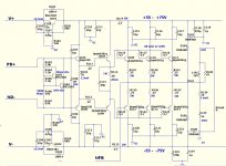
Spent some time on experiments with my initial input buffer design prototype, based on OTA topology (LTP + 3 x current mirrors). After a number of evolutions, came to this setup with rather non-standard arrangement for global NFB and DC servo connections - IPS LTP's emitters. They are roughly 200 mV below zero, but this fact does not cause any problems - servo keeps the whole circuit balanced at all times.
As before, this buffer allows using the amp as inverting, non-inverting, or balanced - both inputs are fully symmetric and always available (see the high level topology diagram).
Prototype measurements and audition showed excellent results. High linearity design with good harmonics distribution. Great phase response. Very low inter-modulation. Even open loop THD is acceptable (open loop gain is 88db).
All measurements are done at 10V RMS, 8 Ohm resistive load (square wave is ~20V p-to-p). I can't go higher at the moment - my load-simulating resistor is rather hot already.
P.S. I also experimented with CFP OPS here - not really successfully. In such wide-bandwidth design it is very difficult to keep it stable. EF rules 😉
This is a very nice piece of work. Congratulations.
Cheers,
Bob
This is a very nice piece of work. Congratulations.
Cheers,
Bob
Thank you Bob.
Cheers,
Valery
I don't think that is as true as people think. At any rate there has to be a much better measure of a person's skill than "did he invent it or not"?
I agree, the two stage CFA with the differential second stage referenced to the rails as in Roy Gosser's patents referenced by Samuel Groner are not in my way of looking at things any different than ground referencing it. IC op-amps can not have a ground pin, it just is not done. 😉
One needs a full circle view where the supplies and ground are one in the same.
Some 50W 24V truck's headlight bulbs used as loads can help sometimes 🙂All measurements are done at 10V RMS, 8 Ohm resistive load (square wave is ~20V p-to-p). I can't go higher at the moment - my load-simulating resistor is rather hot already.
Just take care they have a lower impedance when cold.
Last edited:
Some 50W 24V truck's headlight bulbs used as loads can help sometimes 🙂
Just take care they have a lower impedance when cold.
Ordered some more 50W resistors recently...
Thought about trying the lamps, but it needs more effort... did not happen so far 🙂
I agree, the two stage CFA with the differential second stage referenced to the rails as in Roy Gosser's patents referenced by Samuel Groner are not in my way of looking at things any different than ground referencing it. IC op-amps can not have a ground pin, it just is not done. 😉
One needs a full circle view where the supplies and ground are one in the same.
The only difference being that the ground is quieter than the supply rail, which raises the issue of which approach gives better PSSR performance .
Hi All,
Spent some time on experiments with my initial input buffer design prototype, based on OTA topology (LTP + 3 x current mirrors). After a number of evolutions, came to this setup with rather non-standard arrangement for global NFB and DC servo connections - IPS LTP's emitters. They are roughly 200 mV below zero, but this fact does not cause any problems - servo keeps the whole circuit balanced at all times.
As before, this buffer allows using the amp as inverting, non-inverting, or balanced - both inputs are fully symmetric and always available (see the high level topology diagram).
Prototype measurements and audition showed excellent results. High linearity design with good harmonics distribution. Great phase response. Very low inter-modulation. Even open loop THD is acceptable (open loop gain is 88db).
All measurements are done at 10V RMS, 8 Ohm resistive load (square wave is ~20V p-to-p). I can't go higher at the moment - my load-simulating resistor is rather hot already.
P.S. I also experimented with CFP OPS here - not really successfully. In such wide-bandwidth design it is very difficult to keep it stable. EF rules 😉
😎🙂
[from a hilltop resort in Kathmandu, Nepal]
I read earlier in this thread (from none other than the guru himself, Bob Cordell, I believe), that one of the keys to achieving a stable EF3 output stage is to decouple the rails at the pre-driver, driver and output stages with a heavy RC filter.
However OS's Slewmaster output board manages with only an RC filter between the output and driver. What extra benefit would be achieved adding an additional RC filter between the pre and drivers?
However OS's Slewmaster output board manages with only an RC filter between the output and driver. What extra benefit would be achieved adding an additional RC filter between the pre and drivers?
Attachments
Well it obviously depends on the quality of your supply, the layout of the stages, the wiring runs and another bunch of things.
It is not a law that you HAVE to decouple stuff. If their is no mutual impact it isn't necessary, if there is mutual influence you should try to isolate the stages, and decoupling is ONE technique.
There are no universal answers here.
jan
It is not a law that you HAVE to decouple stuff. If their is no mutual impact it isn't necessary, if there is mutual influence you should try to isolate the stages, and decoupling is ONE technique.
There are no universal answers here.
jan
Just because the problem is possible, doesn't mean that it's actual. OS must have found that for this design, decoupling every collector wasn't necessary. The point is that the person designing and testing the amp knows what the problem is and how to identify it. They can then apply only the fix that is appropriate, no more or no less. Some amplifiers may need more decoupling, but OS tests his designs so he knows what is needed for this one.
I read earlier in this thread (from none other than the guru himself, Bob Cordell, I believe), that one of the keys to achieving a stable EF3 output stage is to decouple the rails at the pre-driver, driver and output stages with a heavy RC filter.
However OS's Slewmaster output board manages with only an RC filter between the output and driver. What extra benefit would be achieved adding an additional RC filter between the pre and drivers?
All of the previous answers are good ones. I recommended it for both driver and pre-driver as being conservative and perhaps a little bit more bullet proof across more different designs and layouts. Note that the current requiresments for the pre-driver and the rest of the circuitry up front are often less than that for the drivers, so we can sometimes afford to use a bit more series resistance in the decoupling filter feeding the pre-driver. It also gives us one more chance to attenuate nasty HF rail stuff.
Cheers,
Bob
May-be we should separate HF decoupling from Ripple Filtering in our points of view on the question ? Andrej noticed on his amp that filtering its drivers introduced some king of 'blur' in the sound quality, and prefered the non filtered version.so we can sometimes afford to use a bit more series resistance in the decoupling filter feeding the pre-driver. It also gives us one more chance to attenuate nasty HF rail stuff.
All this depend a lot of several factors, including the printed board implementation.
On my point of view, this filtering question need both to use our ears and look at our oscilloscopes just before the final design, in an experimental way with real musical signals. ;-)
I have never found a universal best solution i can apply each and every-time.
Last edited:
Amen ...(from none other than the guru himself, Bob Cordell, I believe)
And thanks to mr. Cordell and (Harmon Kardon/sansui) , The forum no
longer needs to fear 😀 the EF3.
In fact , they can audition any "favorite" CFA/VFA IPS-VAS with ease.
Mission accomplished ! 😀
OS
Hi OS, is there a reason why you chose not to decouple the rails between the driver and pre-driver on your Slew-OPS? I.e. is it unconditionally stable without?
Also wondering whether the output base stoppers can be reduced from 4R7 to 2R2 and the driver stoppers from 22R to 10R without any ill effects. If not, would driver-pre-driver collector decoupling allow the base stoppers to be reduced in value, or does one have nothing to do with the other?
Also wondering whether the output base stoppers can be reduced from 4R7 to 2R2 and the driver stoppers from 22R to 10R without any ill effects. If not, would driver-pre-driver collector decoupling allow the base stoppers to be reduced in value, or does one have nothing to do with the other?
Why do you want to reduce of remove the stoppers.
In an EF3 you are playing with fire if you try to do this.
For another practical example, see my e-Amp design. This is a VFA but the same rules apply wrt the OPS.
http://hifisonix.com/ovation-e-amp/
In an EF3 you are playing with fire if you try to do this.
For another practical example, see my e-Amp design. This is a VFA but the same rules apply wrt the OPS.
http://hifisonix.com/ovation-e-amp/
Hi Bonsai, I have poured over your schematic and build instructions previously but will have another read.
I don't want to remove the base stoppers (I recently built the LTT4 project posted in this forum, an EF3 without stoppers on either the outputs or drivers, and I couldn't stabilise it without grafting stoppers on the board).
Voltage will be dropped over the base stopper, limiting peak power, and for that reason I think it would be worth limiting the value to the minimum possible. I believe Bob Cordell has recommended 5R maximum for the output base stoppers. That leads me to think that a somewhat lower value should be achievable in practice, particularly if some other measures are employed.
Many of the EF2 projects with many outputs hanging off the drivers use 2R2 output stoppers. Many of the small EF2 designs seem to get away without any output stoppers at all. Is there any correlation between the number of output pairs and the base stopper values?
EDIT: Bonsai, I also want to add how much I appreciate you taking the time to write up your Ovation project the way you have. In a way it is as instructive as the writings of Cordell and Self. While their books start with simple building blocks and then present more complex variations, you have started with (what I would regard) as a complex design and explained each element. It is a very useful article that I'll keep referring to as my knowledge improves.
Last edited:
Hi OS, is there a reason why you chose not to decouple the rails between the driver and pre-driver on your Slew-OPS? I.e. is it unconditionally stable without?
Also wondering whether the output base stoppers can be reduced from 4R7 to 2R2 and the driver stoppers from 22R to 10R without any ill effects. If not, would driver-pre-driver collector decoupling allow the base stoppers to be reduced in value, or does one have nothing to do with the other?
Ahhh ! I have delved into this quandary. 😀
With no R/C between OP-driver/pre you can get stability with the proper
choice of pre/driver/OP.
PS- you can use NO base stoppers with the R/C.
Adding the R/C allows for a lot of "slop" in component choices.
The 30 YO sansui has no R/C with slow/fast/ slow for pre/driver/OP.
The newer harmon/ kardons use the R/C with fast/ fast/slow.
I was surprised at this "ignorance" of the standard practice , both
use NO base stoppers .... but survived 20-30 years 😱 .
In simulation , it is apparent that local FB through the rails (to the predriver) attributes to any instability in the typical EF3.
Adding the single 4.7R/47u R/C to the "slew" OPS(driver/pre) ... 😕 works ...
5th element's 5ppm VFA blameless all the way to Thimios's 400khz perfect
square waves (CFA) .. my EF3 does what is required - without any issues.
Also , why not assure perfection ... I use the stoppers , as well.
I think the OEM's are just cheap ... and use precision semi choices
to eliminate any component they can get away with. 😀
Edit- create an EF3 that DOES oscillate - find out why it does , and reverse engineer.
OS
Last edited:
Here's a 'real life' test on plain EFs. No drivers or other stuff to confuse matters.Also wondering whether the output base stoppers can be reduced from 4R7 to 2R2 and the driver stoppers from 22R to 10R without any ill effects. If not, would driver-pre-driver collector decoupling allow the base stoppers to be reduced in value, or does one have nothing to do with the other?
http://www.diyaudio.com/forums/solid-state/234408-stability-analysis-ef-output-stages-2.html#post3461363
ostripper, its an EF1 stage which DOES oscillates 😱
Reducing those base resistors WILL reduce stability. If you're not bothered if your amp has hard-to-troubleshoot instability, reduce those base resistors.
You might like to work out how much headroom you lose with 4R7s.
If you want to sim this, be warned that this mostly isn't a general feedback instability but to do with parasitics .. ie really difficult to sim with any confidence.
I prefer NOT to have to deal with parasitics. It's difficult enough managing my beloved 'pure Cherry' 🙂
I usually don't decouple earlier stages either.
Last edited:
Here's a 'real life' test on plain EFs. No drivers or other stuff to confuse matters.
http://www.diyaudio.com/forums/solid-state/234408-stability-analysis-ef-output-stages-2.html#post3461363
ostripper, its an EF1 stage which DOES oscillates 😱
Reducing those base resistors WILL reduce stability. If you're not bothered if your amp has hard-to-troubleshoot instability, reduce those base resistors.
You might like to work out how much headroom you lose with 4R7s.
If you want to sim this, be warned that this mostly isn't a general feedback instability but to do with parasitics .. ie really difficult to sim with any confidence.
I prefer NOT to have to deal with parasitics. It's difficult enough managing my beloved 'pure Cherry' 🙂
I usually don't decouple earlier stages either.
I see you hit on Ccb , this is quite common on all the OEM's
(I also use it - 47p - badger AND slewmaster).
All 3 "tricks" (Ccb , R/C , and stoppers) make for a very "tame" EF3.
Without , you can actually see "peaking" in the 3-5 mhz+ range in a loop gain analysis.
OS
Last edited:
- Home
- Amplifiers
- Solid State
- CFA Topology Audio Amplifiers