I agree with this as well.
But, I also think damping factor comes into it above a certain point - i.e. below a certain threshold, (e.g. 0.1 Ohms) output Zo you will probably hear nothing.
Theres lots of stories (anecdotal) of people additng in a 0.1 or 0.2 Ohm resistor in series with the speaker because they preferred the sound. No doubt this would be affecting the response and in some cases the speaker behaviour at LF.
NB - I opened a thread up to discuss this stuff - lets transfer the conversation to that one 😉
@ kgrlee
"Sounds" like it Really was special, & successful ! Can you provide a link to the Mirauer info, as i couldn't find Anything ?
"Sounds" like it Really was special, & successful ! Can you provide a link to the Mirauer info, as i couldn't find Anything ?
There wasn't a pre-print so there may no longer be an existing copy.@ kgrlee
"Sounds" like it Really was special, & successful ! Can you provide a link to the Mirauer info, as i couldn't find Anything ?
We did it in conjunction with a Music College to get zillion victims & do multiple presentations.
They were told they were listening to different types of speakers but they were actually carefully matched speakers where we only changed the colour of the grilles and swapped.
I agree with this as well.
But, I also think damping factor comes into it above a certain point - i.e. below a certain threshold, (e.g. 0.1 Ohms) output Zo you will probably hear nothing.
Theres lots of stories (anecdotal) of people additng in a 0.1 or 0.2 Ohm resistor in series with the speaker because they preferred the sound. No doubt this would be affecting the response and in some cases the speaker behaviour at LF.
NB - I opened a thread up to discuss this stuff - lets transfer the conversation to that one 😉
Hi Bonsai,
It is interesting how much difference in frequency response even a 0.2 ohm resistor can make. It is also just not in the bass region. Many speakers go through very significant impedance changes in their crossover region(s). Add this to the fact that speakers quoted as 8 ohms can often fall to as little as 3 ohms (and 4-ohms speakers even lower) and you have a recipe for audible variations in frequency response. Note, in rough terms, a 0.3 ohm source resistance against a 3 ohm loudspeaker impedance minima would result in about 1dB of change.
Cheers,
Bob
Note, in rough terms, a 0.3 ohm source resistance against a 3 ohm loudspeaker impedance minima would result in about 1dB of change.
0.5dB, it's power that matters, not voltage at the load.
0.5dB, it's power that matters, not voltage at the load.
SPL is a 20log() quantity. I think Bob was refering to the SPL at the speaker output.
SPL is a 20log() quantity. I think Bob was refering to the SPL at the speaker output.
Yes, if it's about SPL, then 1dB is correct..
I would like to add that, if 1dB was defined as the lowest level change an human ear can discriminate, we are a lot more sensible to the fundamental/harmonic ratios changes.Note, in rough terms, a 0.3 ohm source resistance against a 3 ohm loudspeaker impedance minima would result in about 1dB of change.
On my personal two ways system, the crossover frequency is 1500Hz. One the attenuator of the horn (medium-treble) was set by measurements, i had to spend more than one month to tune-it finely by ears: A 0.2db change was clearly noticeable.
As well as the change in signature between a hot and cold system, due to the coils and attenuators resistances temperatures changes.
Oh, but we are far away from this topic's subject !
Last edited:
Mark Levinson power amp
I came across a ML power amp schematic that I'm sure I can not post without their lawyers shaking my tree but to my untrained eye it was a VFA followed by a CFA (ten complementary output devices operating Class A). Also I remember the Westrex 3D cutter that had dual cutter coils one for driving and the other for feedback, ie a feedback controlled vinyl disc cutter head. My question is why a VFA and CFA in the same amplifier and why don't we apply feedback from the loudspeaker with this same principle. I have a tri-amp system with the amps at the speakers (no passive x-0ver before the speakers). It would seem to me that a CFA needs to be near the driven load where the cable is kept out of the equation. Thanks for listening. Ray
I came across a ML power amp schematic that I'm sure I can not post without their lawyers shaking my tree but to my untrained eye it was a VFA followed by a CFA (ten complementary output devices operating Class A). Also I remember the Westrex 3D cutter that had dual cutter coils one for driving and the other for feedback, ie a feedback controlled vinyl disc cutter head. My question is why a VFA and CFA in the same amplifier and why don't we apply feedback from the loudspeaker with this same principle. I have a tri-amp system with the amps at the speakers (no passive x-0ver before the speakers). It would seem to me that a CFA needs to be near the driven load where the cable is kept out of the equation. Thanks for listening. Ray
SPL is a 20log() quantity. I think Bob was refering to the SPL at the speaker output.
Correct.
Cheers,
Bob
BTW, this effect can often be seen in Stereophile amplifier reviews done by John Atkinson. He employs a simulated loudspeaker load for one of his frequency response tests.
Hi Bonsai,
It is interesting how much difference in frequency response even a 0.2 ohm resistor can make. It is also just not in the bass region. Many speakers go through very significant impedance changes in their crossover region(s). Add this to the fact that speakers quoted as 8 ohms can often fall to as little as 3 ohms (and 4-ohms speakers even lower) and you have a recipe for audible variations in frequency response. Note, in rough terms, a 0.3 ohm source resistance against a 3 ohm loudspeaker impedance minima would result in about 1dB of change.
Cheers,
Bob
I've got some low ohm resistors. I might try it a bit later today and report back.
All my amps have output inductors of between 0.6 and 1uH so Zo is increases at HF - I am interested to see if the lower damping affects the bass sound.
(Looking forward to your latest book update BTW)
This can be the case with tweeters or mediums , where some manufacturers can use the voice coil inductance to cheat about their speaker's impedance, but, on my experience, 8 Ohms boomers have most of the time DC resistance around 6 Ohms.Add this to the fact that speakers quoted as 8 ohms can often fall to as little as 3 ohms...
An example witch goes in your direction is my Jbl 2426J compression driver quoted as 16 Ohms in catalogs, that i use as a 8 Ohm speaker because its DC of 6 Ohms (if i remember well).
This can be the case with tweeters or mediums , where some manufacturers can use the voice coil inductance to cheat about their speaker's impedance, but, on my experience, 8 Ohms boomers have most of the time DC resistance around 6 Ohms.
An example witch goes in your direction is my Jbl 2426J compression driver quoted as 16 Ohms in catalogs, that i use as a 8 Ohm speaker because its DC of 6 Ohms (if i remember well).
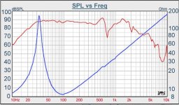
The one (below) I am testing in my new ported enclosure stresses the amp
out at 10hz and 100hz (as predicted by the OEM imp. plot).
Also , at the box/driver Fc , very little load at all - real wide range of I (on the amp).
It does read 6.5R with a DMM , so one might expect the same with it
actually running at Xmax .... NOPE.
BTW - it is a "free" tangband WT-644f sub (8R rated).
OS
Attachments
OS,
That is one ugly impedance curve you got there on that speaker. I can see where you are going to need gobs of power to drive that speaker below resonance and lots of eq to get there. Why use this speaker for a sub application, it doesn't appear that is where it really wants to work?
That is one ugly impedance curve you got there on that speaker. I can see where you are going to need gobs of power to drive that speaker below resonance and lots of eq to get there. Why use this speaker for a sub application, it doesn't appear that is where it really wants to work?
OS, there's something not quite right with that measurement. I take it you read 6R5 Rdc.The one (below) I am testing in my new ported enclosure stresses the amp out at 10hz and 100hz (as predicted by the OEM imp. plot).
Also , at the box/driver Fc , very little load at all - real wide range of I (on the amp).
It does read 6.5R with a DMM
Have you measured the Impedance plot yourself of your actual unit with 6R5 Rdc? The impedance plot should show slightly more than 6R5 at 100Hz
______________
Duu.uh!! The Impedance scale is on the Right side. Everything looks OK.
Last edited:
Cone is fractionating heavily at 550Hz too !The one (below) I am testing in my new ported enclosure stresses the amp.
Ported means Bass reflex ? I don't see any charge at the resonance, so i wonder if your measure was made in free air ?
Or is-it charged at 100 Hz ? ;-)
Don't see anything abnormal, it is probably a long coil in a little gap and high Q.
Last edited:
OS,
That is one ugly impedance curve you got there on that speaker. I can see where you are going to need gobs of power to drive that speaker below resonance and lots of eq to get there. Why use this speaker for a sub application, it doesn't appear that is where it really wants to work?
I got it out of a sub ? It is the common logitech Z series subwoofer
...found on the street. I just want 30hz (like the original).
I am giving it "gobs" - full "honeybadger" BJT 150w amp. Built to
run 250+/4R.
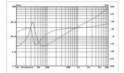
Strange, the dayton 10" I eventually want to replace it with has a similar
curve (4R - "load" that amp down - below) 😀
I also have a direct jack to the sub to test future CFA's for
LF "duty".
PS - this e-waste sub seems to have same free-air imp. plot as
most of the PE "golden subs" $$$ 😀 - the "Z peak" is lower with larger
woofers (lower Fc) ??
(below 2) , for laughs and giggles (I could not afford it) the Hivi 10 (250$)
has nearly the same curve as my "junk" 10" 😀
So much for my confusion .. sorry ???
OS
Attachments
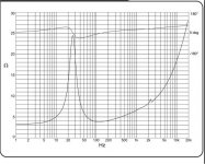
This is the free air impedance plot and not the in box impedance I assume? If it was in a ported box as Esperando asked you would see a double hump around the port tuning. The fs looks to be around 25hz.
This is the free air impedance plot and not the in box impedance I assume? If it was in a ported box as Esperando asked you would see a double hump around the port tuning. The fs looks to be around 25hz.
You know your stuff. 🙂
My point is ... (with a AC watt meter as test) the amp is seeing a load equivalent to 5-30R from below the box tuning (@29hz) to 120hz.
The 10cm port blows out candles at 6 meters -28hz , that must be the
tuning.
PS - I do see the "double hump" in bassbox .... the amp's response
confirms this (10-120hz sweep - full xmax 150W).
It is wise to simulate @ 2-3R for OPS 😀 .
OS
OS,
If you want to retune the speaker for a lower frequency just add some mass to the cone and you can move that down. But how low do you really want to go? Things start to fall off shelves and other things will rattle and drive you nuts.
If you want to retune the speaker for a lower frequency just add some mass to the cone and you can move that down. But how low do you really want to go? Things start to fall off shelves and other things will rattle and drive you nuts.
- Home
- Amplifiers
- Solid State
- CFA Topology Audio Amplifiers