I know , I could even stuff (the box) more .. who needs 20hz ?OS,
If you want to retune the speaker for a lower frequency just add some mass to the cone and you can move that down. But how low do you really want to go? Things start to fall off shelves and other things will rattle and drive you nuts.
The amps OPS seems to get along fine with even sustained Xmax.
This was my first attempt to tune my own box (and it came within a few hz).
Same as amp simulations -the real world is 10% off .
Having a free sub will allow me to port some
of these amps to LF use.
Bob was right , even an semi-efficient 8R driver ported setup can
heat up an amp (especially during non-musical testing) 😱.
Over -design is not a waste of time (add those extra output pairs) 😱 .
PS - I tried movies with the sub - I'm happy ... wow !
OS
On my opinion, it would be a strange choice to use a CFA for sub. Its really the place where LTP shows their PSRR advantages, with no need for "fast".Having a free sub will allow me to port some
of these amps to LF use.
On my opinion, it would be a strange choice to use a CFA for sub. Its really the place where LTP shows their PSRR advantages, with no need for "fast".
Ahhh , but if you are using the "cost cutting" attributes of the "alien" CFA
tech to make a 10$ /100w sub amp - it DOES make sense (below).
PS - 4 transistors/1 IC + 5 transistors for the EF2 = .01% 20hz w/1 mv
offset. (tiny board for plate amps).
Everyone (including me) discusses PPM/psrr ... CFA can go "cheap", as well. 😀
OS
Attachments
If you want lower distortion from your driver in a tuned port enclosure..... rather than max flatness or freq extention... tune it to the the side of resonance. IIRC... lower side.
-RNM
-RNM
If you want lower distortion from your driver in a tuned port enclosure..... rather than max flatness or freq extention... tune it to the the side of resonance. IIRC... lower side.
-RNM
Hey, I lucked out 🙂 ... resonance is 32hz , my tuning is @26-28hz.
This happened by accident (I read later) ... that a port will "appear"
to be longer (tuned lower) than the math would predict.
... vent tuning (link)
Just like the amps , you must build it !! 😀 (math is not perfect)
OS
OS,
I think the effective tube length is length of tube plus 2X the radius of the tube. So a 2" diameter tube 8" long would be equal to a 10" long tube.
I think the effective tube length is length of tube plus 2X the radius of the tube. So a 2" diameter tube 8" long would be equal to a 10" long tube.
@ ostripper
Yeah, gotta take notice of the End correction 😉 I've always tuned about 5Hz or so lower than simmed, because the T/S parameters get altered with voice coil rise, which increases fs etc & therefore fb !
Un damped boxes are better for subs, due to the material in damped boxes moving with the constantly changing air pressure. This causes unpredictable changes in the response !
Whatever you try, and there is a infinite number of combinations, i think i'll always have best results (the best compromise between frequency response, damping and step response etc.), when a bass reflex is tuned for OPR alignment. (when the two impedances peaks have the same level).Hey, I lucked out 🙂 ... resonance is 32hz , my tuning is @26-28hz.
Note that if you go for resonance compensation network, and despite the new (upper) resonance frequency of the Loudspeaker in its BR enclosure, you don't have to change the L& C values of it. (I'm sure the neysayers will explain it, hehe !)
Just adjust the value of the resistance for a flat impedance curve.
To conclude about this subjet, so far from this topic's one, a fantastic web site with near everything about speakers and enclosures, including a huge database of THIELE et SMALL parameters for them: Page d'accueil d'un site sur la conception des baffles DIY
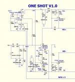
Continuing "outside the box" - balanced ultra-linear
Hi All,
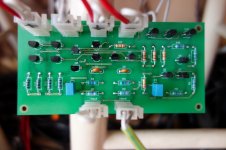
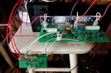
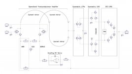
Spent some time on experiments with my initial input buffer design prototype, based on OTA topology (LTP + 3 x current mirrors). After a number of evolutions, came to this setup with rather non-standard arrangement for global NFB and DC servo connections - IPS LTP's emitters. They are roughly 200 mV below zero, but this fact does not cause any problems - servo keeps the whole circuit balanced at all times.
As before, this buffer allows using the amp as inverting, non-inverting, or balanced - both inputs are fully symmetric and always available (see the high level topology diagram).
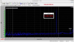
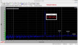
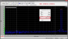
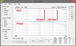
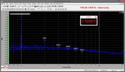
Prototype measurements and audition showed excellent results. High linearity design with good harmonics distribution. Great phase response. Very low inter-modulation. Even open loop THD is acceptable (open loop gain is 88db).
All measurements are done at 10V RMS, 8 Ohm resistive load (square wave is ~20V p-to-p). I can't go higher at the moment - my load-simulating resistor is rather hot already.
P.S. I also experimented with CFP OPS here - not really successfully. In such wide-bandwidth design it is very difficult to keep it stable. EF rules 😉
Hi All,
Spent some time on experiments with my initial input buffer design prototype, based on OTA topology (LTP + 3 x current mirrors). After a number of evolutions, came to this setup with rather non-standard arrangement for global NFB and DC servo connections - IPS LTP's emitters. They are roughly 200 mV below zero, but this fact does not cause any problems - servo keeps the whole circuit balanced at all times.
As before, this buffer allows using the amp as inverting, non-inverting, or balanced - both inputs are fully symmetric and always available (see the high level topology diagram).
Prototype measurements and audition showed excellent results. High linearity design with good harmonics distribution. Great phase response. Very low inter-modulation. Even open loop THD is acceptable (open loop gain is 88db).
All measurements are done at 10V RMS, 8 Ohm resistive load (square wave is ~20V p-to-p). I can't go higher at the moment - my load-simulating resistor is rather hot already.
P.S. I also experimented with CFP OPS here - not really successfully. In such wide-bandwidth design it is very difficult to keep it stable. EF rules 😉
Attachments
-
 03-zDSC03211.JPG288.6 KB · Views: 353
 -
 03-zDSC03209.JPG313.5 KB · Views: 271
 -
 03-THD-9.0K.JPG276 KB · Views: 187
 -
 03-THD-4.5K.JPG280 KB · Views: 203
 -
 03-THD-1.0K.JPG291.1 KB · Views: 254
 -
 03-SQR.JPG139.3 KB · Views: 285
 -
 03-IMD-14.15.JPG298.3 KB · Views: 495
 -
 03-Bode.JPG123.9 KB · Views: 545
 -
 00-Principle.jpg88.5 KB · Views: 573
 -
 04-THD-1.0K-OL.JPG352.1 KB · Views: 351
That is a lot like Samuel Groner's approach in his articles:
A new audio amplifier topology with push-pull transimpedance stage - Part 1: Introduction | EE Times
It is essentially one of the very best ways to boost open-loop gain without losing a lot in terms of BW and anything else, so it's no surprise you'd get good high order harmonic suppression.
I've seen one or two of OS's designs with cascaded LTP's which is in the same family of gain boosting techniques. Cascaded stages are used to boost gain rather than increasing gain at the stages themselves; this approach allows you to optimize each stage in more detail without distortion increasing with stage gain (which ruins the point of more gain in the feedback loop).
That is a lot like Samuel Groner's approach in his articles:
A new audio amplifier topology with push-pull transimpedance stage - Part 1: Introduction | EE Times
Why is this called new ???? 😕 One example Ive seen is by an australian engineer who proposed this scheme long before the stated date of Samuel Groner article. This engineer even has it published somewhere on the internet. Maybe I can find it again.
Why is this called new ???? 😕 One example Ive seen is by an australian engineer who proposed this scheme long before the stated date of Samuel Groner article. This engineer even has it published somewhere on the internet. Maybe I can find it again.
Read the first comment after the article.
Read the first comment after the article.
I cant recall the name but I assume from your post that GK was the other designer.
From our self-exiled Glenn Kleinschmidt! Finally found his webpage again. Thanks!
Here it is:
A New Topology For A Current Feedback Amplifier
Personally, instead of knowing the person who first invented somesuch topology, I would rather have a list of people who understood, could implement, adjust, and adapt the given topology in an application. Then I'd put them in my contact list! I think people get carried away with prestige a lot of time.
From our self-exiled Glenn Kleinschmidt! Finally found his webpage again. Thanks!
Here it is:
A New Topology For A Current Feedback Amplifier
Personally, instead of knowing the person who first invented somesuch topology, I would rather have a list of people who understood, could implement, adjust, and adapt the given topology in an application. Then I'd put them in my contact list! I think people get carried away with prestige a lot of time.
Correct but then again the inventor is near always the one that best understands and probably first implemented the topology.
I don't think that is as true as people think. At any rate there has to be a much better measure of a person's skill than "did he invent it or not"?
Structured approach
keantoken, thank you for the link.
I was not aware of this particular material, however some ideas are similar. There are also some interesting (at least for me 😉) thoughts on compensation in such designs there.
Key principles, I used in my design, are rather simple:
1) Keep clearly separated and all-sufficient stages (trans-conductance, trans-impedance, power-section);
2) Maintain as much linearity and overall quality as possible for each stage;
3) Apply global NFB to low-impedance, current-sensing point (in my case - points).
All compensation is only applied within the trans-impedance stage (Miller + shunt, very light ones, for maintaining stability), plus small cap (5.1 pF) in parallel with global NFB resistor (removing slight overshoot at fast fronts).
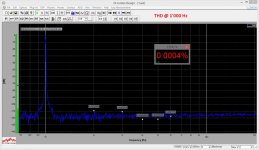
It results in around 88db open loop gain with roughly 0.3% THD. Then dropping 60db with global NFB and reaching 0.0004% THD @ 1KHz.
Well, we all know that THD as a single measured parameter does not guarantee good sound, however combination with good phase response, high slew rate, negligible IMD, s/n ratio and right approaches to power supply and overall build, makes it something worth auditioning 🙂
That is a lot like Samuel Groner's approach in his articles:
A new audio amplifier topology with push-pull transimpedance stage - Part 1: Introduction | EE Times
It is essentially one of the very best ways to boost open-loop gain without losing a lot in terms of BW and anything else, so it's no surprise you'd get good high order harmonic suppression.
I've seen one or two of OS's designs with cascaded LTP's which is in the same family of gain boosting techniques. Cascaded stages are used to boost gain rather than increasing gain at the stages themselves; this approach allows you to optimize each stage in more detail without distortion increasing with stage gain (which ruins the point of more gain in the feedback loop).
keantoken, thank you for the link.
I was not aware of this particular material, however some ideas are similar. There are also some interesting (at least for me 😉) thoughts on compensation in such designs there.
Key principles, I used in my design, are rather simple:
1) Keep clearly separated and all-sufficient stages (trans-conductance, trans-impedance, power-section);
2) Maintain as much linearity and overall quality as possible for each stage;
3) Apply global NFB to low-impedance, current-sensing point (in my case - points).
All compensation is only applied within the trans-impedance stage (Miller + shunt, very light ones, for maintaining stability), plus small cap (5.1 pF) in parallel with global NFB resistor (removing slight overshoot at fast fronts).
It results in around 88db open loop gain with roughly 0.3% THD. Then dropping 60db with global NFB and reaching 0.0004% THD @ 1KHz.
Well, we all know that THD as a single measured parameter does not guarantee good sound, however combination with good phase response, high slew rate, negligible IMD, s/n ratio and right approaches to power supply and overall build, makes it something worth auditioning 🙂
Evil CFP
Damir, you were right, CFP is too "cranky" for such design. EF shows much more stability. I will publish some prototype-based results later on...
Valery, I think that the main problem why I can't get your amp stable is CFP output stage.
I will try more but first what came to my mind is to change it to ordinary EF, maybe CFP is not suitable for the CFA. With CFP I need to add heavy shunt capacitive compensation and some RC on the drivers base to the ground, and still there are small glitches near the crossover points.
Damir
Damir, you were right, CFP is too "cranky" for such design. EF shows much more stability. I will publish some prototype-based results later on...
- Home
- Amplifiers
- Solid State
- CFA Topology Audio Amplifiers