This is indeed what happens.
But if you use the techniques in Self (simming thermal conductance & lag) and Cordell (matching Vbes) you can with care get an EF2 to remain in the low THD slot under dynamic conditions, hot or cold.
kgrlee, do you mean, that those techniques (simming thermal conductance & lag and/or matching Vbes) will allow THD staying stable enough even when the bias circuit decreases the quiescent current?
Because it will decrease it... regardless...
I understand it exactly the same way, as mentioned in post #5894.
Thermal feedback is relatively slow, and this is a major factor of having the OPS quiescent current drop below the nominal level, after some long high signal heats up the heat-sinks and then disappears.
What we need is a SMART bias circuit.... one that takes the inputs of heat and thermal runaway conditions and also drives the OPS bias up when signal drops and temp is high... fast.
Right now I have to bias the OPS higher than needed so the min drop is still up enough to keep THD low.
THx-RNMarsh
Am I the only one who has noticed that since Waly re-entered the fray, the noise level on this thread has gone through the roof yet again?
Indeed, and that's because you and others want to keep this thread as a back patting, self gratifying, CFA fan club, rather than have any significant technical discussion. To any technical facts or comments, that are against the CFA the myths and legends (not to mention those coming on a direct collision course with 75 years of EE theory and practice), the CFA fan club members are either responding with personal attacks, or simply by ignoring (jcx, Mr. Cordell, Dave Zan).
No whining !
All bring different experiences, perspectives, assumptions, questions and knowledge. Some may be correct but preface or interject this anti-fan club hatred into everything they have to say. It doesnt work for most people... esp not for those of a fan club. 🙂
We are all mostly smart adults here... just put out your facts and education without whining.
-RM
_________
I am somebody, somewhere.
Last edited:
I understand it exactly the same way, as mentioned in post #5894.
Thermal feedback is relatively slow, and this is a major factor of having the OPS quiescent current drop below the nominal level, after some long high signal heats up the heat-sinks and then disappears.
Use ThermalTrak transistors from Onsemi, thermal feedback is quicker. Maybe you can use OPS from my TT amp? http://www.diyaudio.com/forums/solid-state/182554-thermaltrak-tmc-amp-15.html#post3065943
Use ThermalTrak transistors from Onsemi, thermal feedback is quicker. Maybe you can use OPS from my TT amp? http://www.diyaudio.com/forums/solid-state/182554-thermaltrak-tmc-amp-15.html#post3065943
Was told a long time ago that those type OPS transistors were not made any more. NOS somewhere or was I told wrong?
Would it mean that the bias dip down after signal isnt avoided but only its duration of low bias is shortened.
barring a smart(er) bias circuitry....perhaps moving to neg temp coeff devices in the OPS is a better solution.
THx-RNMarsh
Last edited:
Use ThermalTrak transistors from Onsemi, thermal feedback is quicker. Maybe you can use OPS from my TT amp? http://www.diyaudio.com/forums/solid-state/182554-thermaltrak-tmc-amp-15.html#post3065943
Thermaltrak is actually an interesting option, I thought about them. Difficult to buy here. I'd like to try them some day though... will check your TT OPS design out then
Yes. Read Self & Cordell for the tools to design this but take their final solutions with a pinch of salt.kgrlee, do you mean, that those techniques (simming thermal conductance & lag and/or matching Vbes) will allow THD staying stable enough even when the bias circuit decreases the quiescent current?
Because it will decrease it... regardless...
You can even design it so the bias circuit increases quiescent current when hot 😱
But the technology & knowledge is not mature so you need a a wide 'low THD bias window'. Hence EF2 instead of CFP.
You can easily test this. Set your gear up to measure THD at 1 watt or less. Then without touching anything, up the power to 1/3 max power until everything is stinking hot. Reduce the input signal back to the 1 watt setting and immediately see what your THD is.
Your THD analyser must be happy with 20+dB overload but in most cases, you can do this within 1s of the 1/3 power warmup.
______________
All, please continue to ignore da 'yus are all idiots & deaf' MikeK lookalikes until they start posting useful stuff instead of pedantic/semantic sh*t.

Gentlemen, may I remind you that participation in a thread is not mandatory, that you have the option of adding a member to your ignore list if you find their opinions differ greatly from theirs and that Moderators do not require extra work. I am hoping this is understood as the next step is to give infractions. Let's avoid that.
The only amps I've built from scratch was LEACH LTIM and SUPERAMP and The good Dr. Leach must have changed every part (mostly resistors and caps) on the board several times over the course of two years. I changed parts to the point of lifting the pc traces from off the circuit board. Don't want to go through that again. Input filters and lead and lag compensaition caps several times. Fortran simulation software on mainframes was his only sim back then. YES, it got him in the ballpark but the work was only halfway done. After all this talk and several hundred pages of posts, then how many have actually built something with real parts on a real test bench and anything empirically measured including LISTENING TO MUSIC through it in any double blind listening test? Very few! OS and maybe one or two others. GRH
my first DIY amp built from scratch was a CFA type from the RCA transistor databook,
then the Pioneer SX770 clone, but when i discovered the Leach Superamps, i never looked back,
i also built Dan Meyer's Tigersaurus but they were used for PA duties, not for serious music listening.....
i am amazed at how proponents of either type are fighting tooth and nail over which is superior over the other,
imho a needless exercise as both types can be just as enjoyable as the other....
this thread saw one member banned, several members binned several times, thread was closed several times....
it is as if both sides have a commercial agenda to promote.....😱
Hi, KGRLee,
I just did what you suggested within the past hour. Running around 30W/8 Ohm to warm it up, It took 45 seconds for the bias to reach stable set point after signal removal -- the bias dipped to minimum and then to set point.
Of course, different heat-sink size has a large affect on the outcome. [Maybe a fan isnt such a bad idea, after all. They now make fans that are super quiet.]
PS - I have the 6th edition by D.Self and I am looking at it now... gimmie a minute.
THx-RNMarsh
Last edited:
Yes. Read Self & Cordell for the tools to design this but take their final solutions with a pinch of salt.
You can even design it so the bias circuit increases quiescent current when hot 😱
But the technology & knowledge is not mature so you need a a wide 'low THD bias window'. Hence EF2 instead of CFP.
OK, I think I finally see what you mean 🙂 I've read both books (well, not the latest edition). Of course one can design the Vbe multiplier the way that it will be much less sensitive and will decrease the bias just a bit when hot (not allowing runaway though). In this case the negative effect will be much less when "heating" goes off.
And of course, EF2 is "wider window"... but I like CFP - my impression it sounds good. It also allows thermal sensing from the drivers, making the thermal loop faster... so... a matter of the right compromise, until somebody invents a better concept ))
BTW, got a new FFT/ THD measurement tool today. Will run some measurements tomorrow
Last edited:
Ok here's some info..... from D.Self 6th edition -- His summary of output distortion shows the CFP to be the lowest... 1/2 of EF under his test conditions.
he also uses the CFP output on his amps.
Large signal gain vs output:
EF
View attachment EF gain vs output.pdf
CFP
View attachment CFP gain vs output.pdf
Looks better to me, also.
But he says trouble starts when you go to more than two parallel output devices... but doesnt know why, yet.
THx-RNMarsh
Last edited:
There are 2 quite separate issues.OK, I think I finally see what you mean 🙂 I've read both books (well, not the latest edition). Of course one can design the Vbe multiplier the way that it will be much less sensitive and will decrease the bias just a bit when hot (not allowing runaway though). In this case the negative effect will be much less when "heating" goes off.
- matching the Vbe multiplier to the output stage. Cordell is most detailed on this. It affects the bias when the amp has settled to whatever steady state signal. If you use the amp for sine waves this is sufficient.
- But if the signal changes, the thermal conditions also change and the bias must change with it. If the time constants aren't matched, you will have more distortion until the amp settles down to a new (hopefully) steady state. Where this hasn't been carefully thought out, the misbiased period can be 45s as Mr. Marsh to minutes as with Self
When the amplifier is switched on and begins to apply sinewave power to a load, the crossover spikes (generated by the deliberate underbiasing) will be seen to slowly shrink in height over a couple of minutes as the drivers warm up
Rather than pontificate on what I think is right, I offer my 1W THD test after high power as something all real PA designers should do.
______________
It may be that you like the slightly higher THD after a burst of high power with CFP. Or the higher THD at low level shown in Self's fig 5.39 & 5.40 4th ed that I posted slightly earlier.And of course, EF2 is "wider window"... but I like CFP - my impression it sounds good. It also allows thermal sensing from the drivers, making the thermal loop faster... so... a matter of the right compromise,
Increased THD at low level, possibly due to xover, is known to be particularly audible to true golden pinnae in DBLTs.
Mr. Marsh, that's the bit I'm really interested to know if Self has done any new 'real life' work on in his 6th ed. I posted the pics in #5892. In the 4th ed, they are in Chapter 5 Output Stage I
You don't want the 'thermal loop faster'. You want it matched to the output stage/drivers etc. And the reason you want that is so its never improperly biased. And the reason you want that is for low THD cos xover is particularly nasty sounding.
Last edited:
BTW, got a new FFT/ THD measurement tool today. Will run some measurements tomorrow
Great.... what are you going to use?
-RM
or simply by ignoring (jcx, Mr. Cordell, Dave Zan).
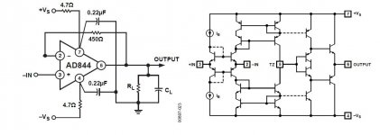
Question for you. Below I’ve got a very simple circuit so called CFA as a simple voltage follower removing all unnecessary complications. 450 Ohm feedback gives nice response. Now I make it 20k and gee wiz the BW is down over 10X and now I have to give a huge input step to make it slew. Wazzup, please explain this behavior without referring to the current in the feedback resistor because after all it can’t matter, the feedback is voltage. Actually caught MikeK on this, his knee jerk reaction was that the current in the feedback resistor did not charge the comp cap (he corrected himself but went on ignoring it).
I will go back to simply ignoring you.
Attachments
I have just taken this VFA amp and looked at it... found the bias adjust and tweaked it with loads and monitored the THD. No attempt to improve it.
If one has an existing amp/design -- I found that slightly high side biasing while still in the null THD region is best. bias drops to lower level but not too low.... the THD still is respectable. Its when the bias is on the low side of the THD/bias range that greater trouble will appear... the rise in THD is steep on the low side.
______________________________
This all brings up DBLT ---- these could all be considered now as null and void.... if there was not a constant load on the amps being compared when listening is switched back and forth. Such as switching in a load R when the other amp is switched in.... music being played into both amps all the time.
The times between selection/comparison is a cooling off period.... going back and forth makes both amps sound their worst with THD rising and falling. And, if the period between comparisons were made small... maybe under a minute... the amps may be at minimum bias most of the time.
Could it explain why some like to do comparisons over long time periods and keep amps on all the time rather than A-B back and forth at random intervals? maybe.
What a mess this is becoming!
THx-RNMarsh
Last edited:
This is part of how I do amps with less change of THD with temp.If one has an existing amp/design -- I found that slightly high side biasing while still in the null THD region is best. it drops to lower level but not too low.... the THD still is respectable. Its when the bias is on the low side of the THD/bias range that greater trouble will appear... the rise in THD is steep on the low side.
This all brings up DBLT ---- these could all be considered now as null and void.... if there was not a constant load on the amps being compared when listening is switched back and forth. Such as switching in a load R when the other amp is switched in.... music being played into both amps all the time.
The times between selection/comparison is a cooling off period.... going back and forth makes both amps sound their worst with THD rising and falling. And, if the period between comparisons were made small... maybe under a minute... the amps may be at minimum bias most of the time.
Actually, an amp with carefully thought out bias which remains in the 'low THD valley' would not be as badly affected. IMHO, this is a better amp and should rightly come up the winner in DBLT.
Actually, an amp with carefully thought out bias which remains in the 'low THD valley' would not be as badly affected. IMHO, this is a better amp and should rightly come up the winner in DBLT.
I would think it ought to come up the winner also. The problem for consumers is that it appears not many biasing schemes in amps are so carefully done..... might most be a mess in this context? Esp when price point is a selling concern... thus, heat sink minimal and so is bias etc.
yet, when they can all measure at a perfect -100dB and lower under steady-state conditions of bench testing.... but change dynamically the THD due to bias behaviour under listening conditions. So is it the amp which changes the THD least under dynamic conditions the best sounding? Based upon static THD etal tests, the numbers show we should not be able to hear any differences between similar THD amps. But people do hear differences... could this help explain the conflict?
THx-RNMarsh
- Home
- Amplifiers
- Solid State
- CFA Topology Audio Amplifiers